I recently started with the Arduino hardware and decided that I needed to create something electronic to command from this specific hardware. Since I am a software geek, I immediately came up with the idea to visualize a byte by using 8 LEDs. I also wanted a simple switch in the design so I could give it some special function, although a single switch isn’t offering very much functionality. So the first design used a broadboard and lots of cables to connect it all and looks something like this:
 Yeah, that’s a lot of cables. And 8 LEDs, 9 resistors and a switch. It’s nothing spectacular, though. But this design does need to use 9 pins from my Arduino board, making it a bit pin-hungry. You might want to prefer to have all communication to go through a single pin, plus two more for ground and power. But I decided that I just need an experimental thing that would use several pins.
When you look at its schematics, it looks like this:
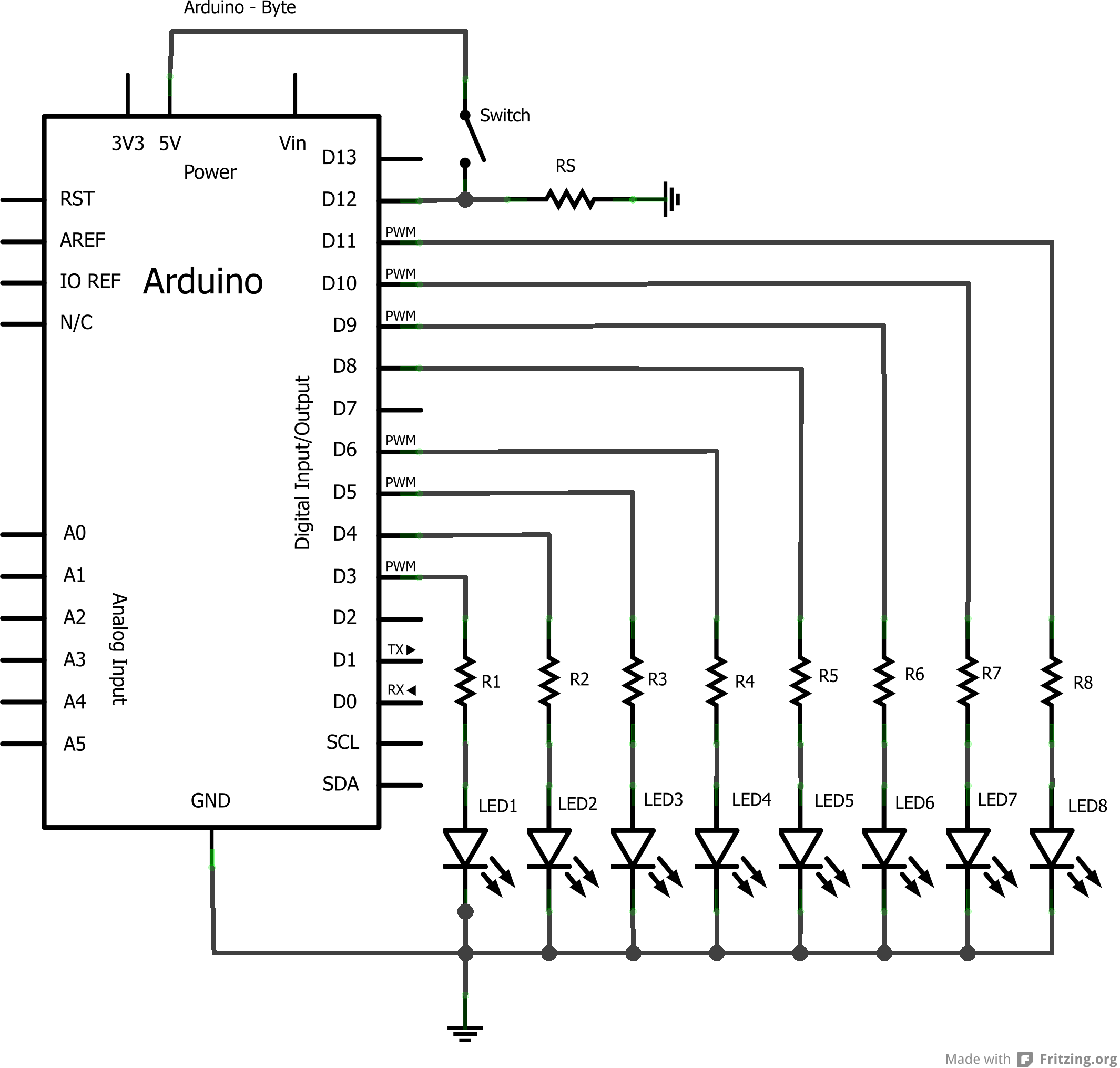 And now, weeks after creating this design, I still wonder why I added a resistor between the switch, pin 12 and ground. Then again, if I would use pin 12 as an analog input, I would not just get a signal when someone presses the button, but also a very low signal related to the number of LEDs that are burning. That’s an interesting concept but I still have to test it.
However, this setup isn’t very practical. All those wires, the LEDs that are a bit loose within the board and the switch that didn’t really want to stay in place made it a bit complex to handle. So I decided to use their services to create a Printed Circuit Board. It would some time for them to fabricate it, though. But still, it would be neat to have some board that I can just click on top of my Arduino.
So, recently I received four of these in my mailbox:
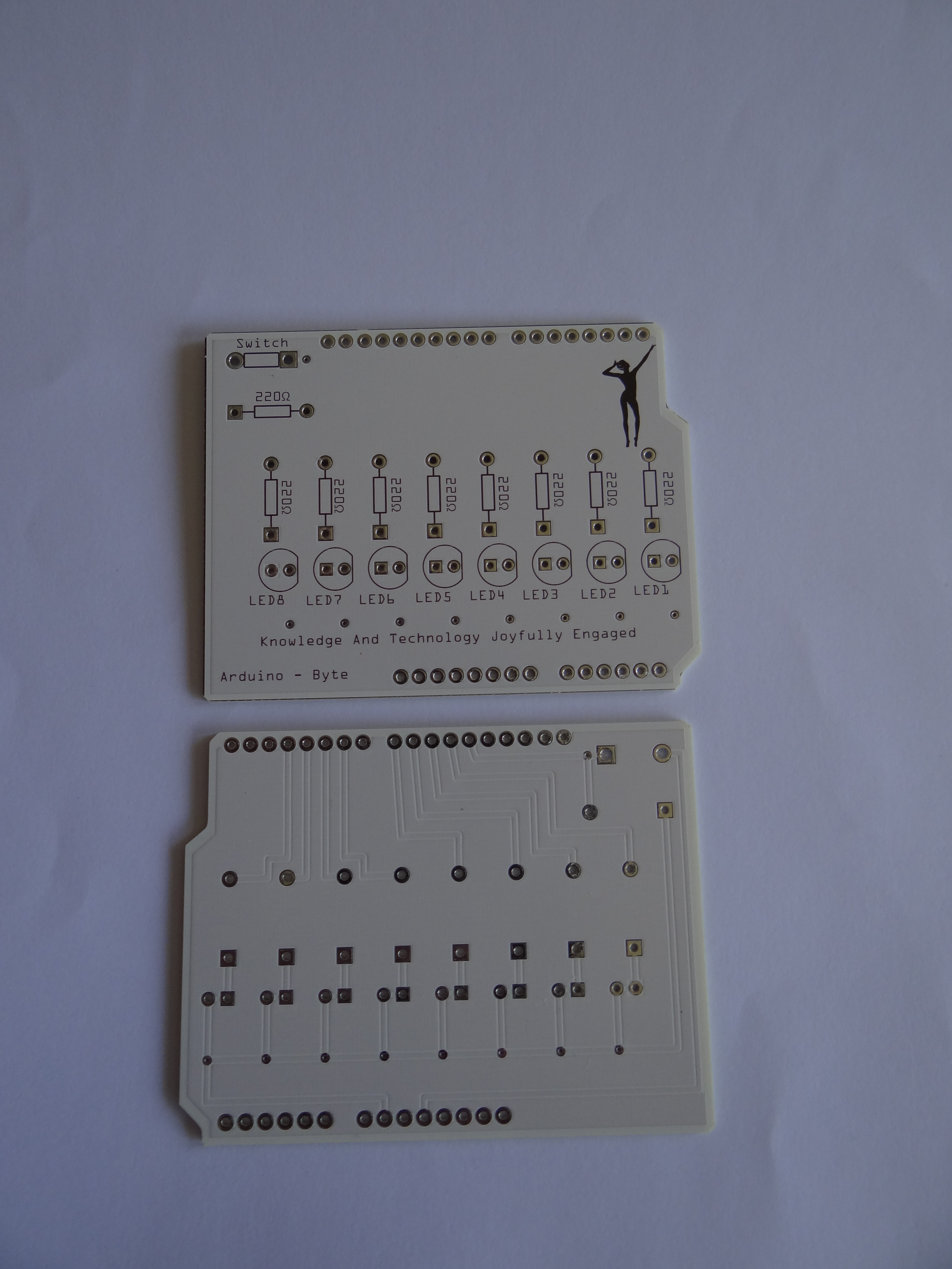 Interesting effect: while the text, logo and instructions are in the front, the actual connections are on the back of this PCB. Did I do this on purpose? No, not really, but I like the effect. It makes the front very smooth, making it even prettier to show. And the logo in the shape of a woman stretching her arms serves the same purpose. Just there to make it look more interesting.
The next step was to add all the LEDs, resistors, the switch and the connecting pins to the PCB. That took some patience with soldiering but I’m happy to say it was a success:
 And yes, the BytePanel code for this project was also quite easy to write, although C/C++ isn’t really my speciality. (I prefer C# or Delphi/Pascal, although I have plenty of experiences with lots of other languages.)
To get this panel to work, I needed a simple piece of code that would set or reset the specific pins that are assigned to the LEDs. And I need input from one pin to detect if the user presses a button. But to make things more practical, I would need a special class for this whole thing. So it was time to write a whole C++ class including header.
class BytePanel
{
  public:
    BytePanel();
    boolean isPressed();
    void reset();
    void loopBits();
    void loopBitsReverse();
    int next();
    int previous();
    void set(byte value);
    void setValue(int bit, boolean value);
  private:
    // The current value
    byte currentValue;
    // The pins
    int pins[8];
    // The bit masks
    int masks[8];
    // The switchpin
    int switchpin;
    void update();
};
This class would need a constructor with the intelligence to set all used pins to either input or output. It would also need to initialize all variables used, including the counter value which remembers the value of this byte.
Next, it would need a simple function to either set or reset a specific LED. This is what setValue is supposed to do. This method is called a few times, since any method that sets or resets bits will need to call this method for every bit.
The function set is a bit more practical, since it accepts a byte value and sets the LEDs to this specific value. However, it will not influence the current value that it stores internally. I could add this but I feel it would give too much functionality to this simple method. Besides, if I want to be able to set any value to the current value then I would need to create a property to get/set the value, instead of keeping it read-only.
Then a few methods called next, previous and reset that will display either the next value, the previous value or reset this counter to 0, which means no LED will be burning. They all call the update method which is used to display the current value. Which is practical if you’ve used the set method to override the value.
Two methods called loopBits and loopBitsReverse will just flash each led for 20 milliseconds. The first method goes from low to high and the other from high to low. These are just fine to call when you start the device, so the user gets a visual sign that the device is working.
This class actually makes it quite easy to use the button to increase the byte value. When the device starts, I just loop the bits before resetting the byte. Then, when the user presses the button I will call the next method to move to the next value. However, I also want to reset the byte, and decided that I need to press the button for half a second before it would reset. And to make things complex, the byte should not increase for as long as I keep pressing the button.
Well, this wasn’t that complex after all:
// Now wait for up to half a second.
 int count=50;
 while(count>0){
   delay(10);
   // Did user release the button again?
   if(!panel.isPressed()) break;
   count--;
 }
 // If count is 0 then the user wanted to do a reset.
 if((count==0)) {
   // Reset the byte.
   panel.reset();
   // Wait for user to release the button.
   while (panel.isPressed())
   {
     delay(10);
   };
 }
Basically, when the button is pressed, I increase the byte. I then enter a loop that will break if the button is released, or else end when it has counted 50 x 10 milliseconds. In the latter case, the counter will have reached zero, thus I need to reset the byte. I also need to wait for the user to release the button again, else the counter will start at one, not zero. (Because the button is pressed when it iterates from the start again.)
It’s not very complicated to do, as you can see. And of course I could add even more functionality. For example, if the user presses the button for half a second, it should light all LEDs and then move in reverse order, thus every new press of the button would call previous to decrease. Press it for half a second again and it will move forward again. And press it for a full second and it will reset itself.
It’s just one button so I can’t add much functionality to it anyways. But I’m still proud of my first Arduino project. It’s small and it looks nice. I can connect just a battery to it, like in the picture, then press the button to show a specific 8-bit value in binary. And… Well, that’s all, actually. 🙂
But what’s more important: I now have a piece of electronics which I can use to write software for! For example, I could use a serial connection to send bytes from the computer to display as bits on this device. Maybe even make it communicate with a second Arduino device so one will send values that the other will display.
And I have three more PCB’s that I can use to create three more of these simple devices.
