Two dice with an ATTiny13

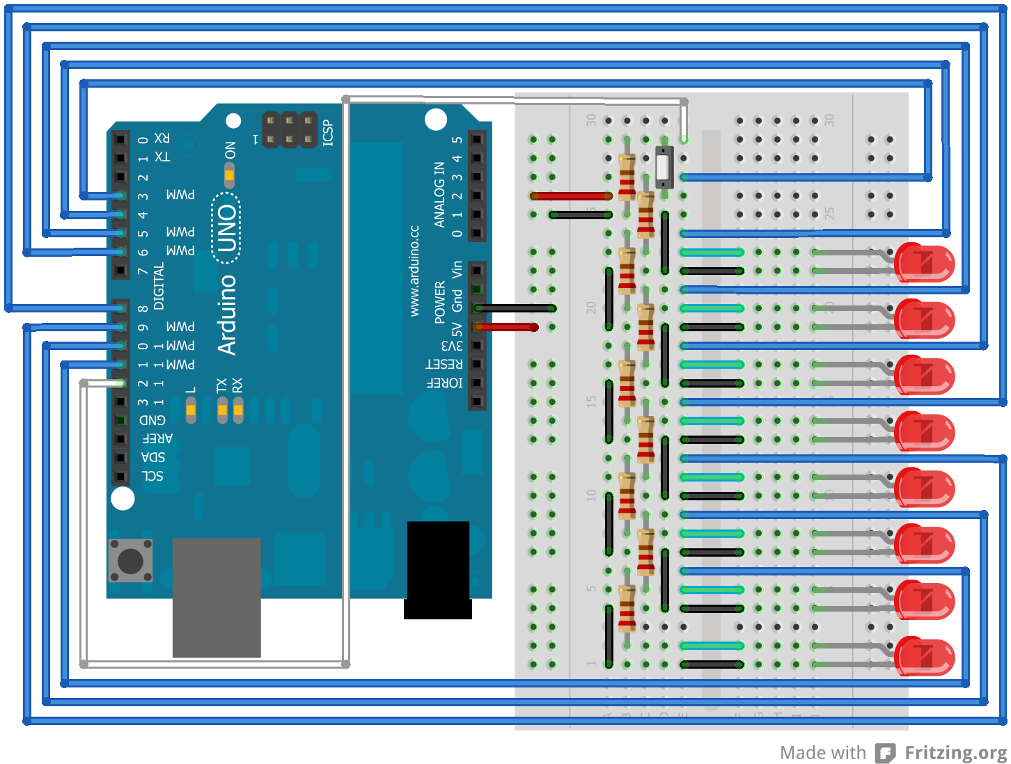
A long time ago, I designed my own board using an ATTiny85, a 74HC595, two buttons and 14 LEDs to create a simple board with 2 6-sided dice. Pressing a button would roll one of the dice. It was fun, but I forgot about that project until I decided to redo it again. And this time, I designed a new, round board that would use capacitive buttons. And the result? This video, this design, this Gerber file (zipped) and this picture:

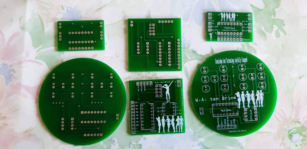
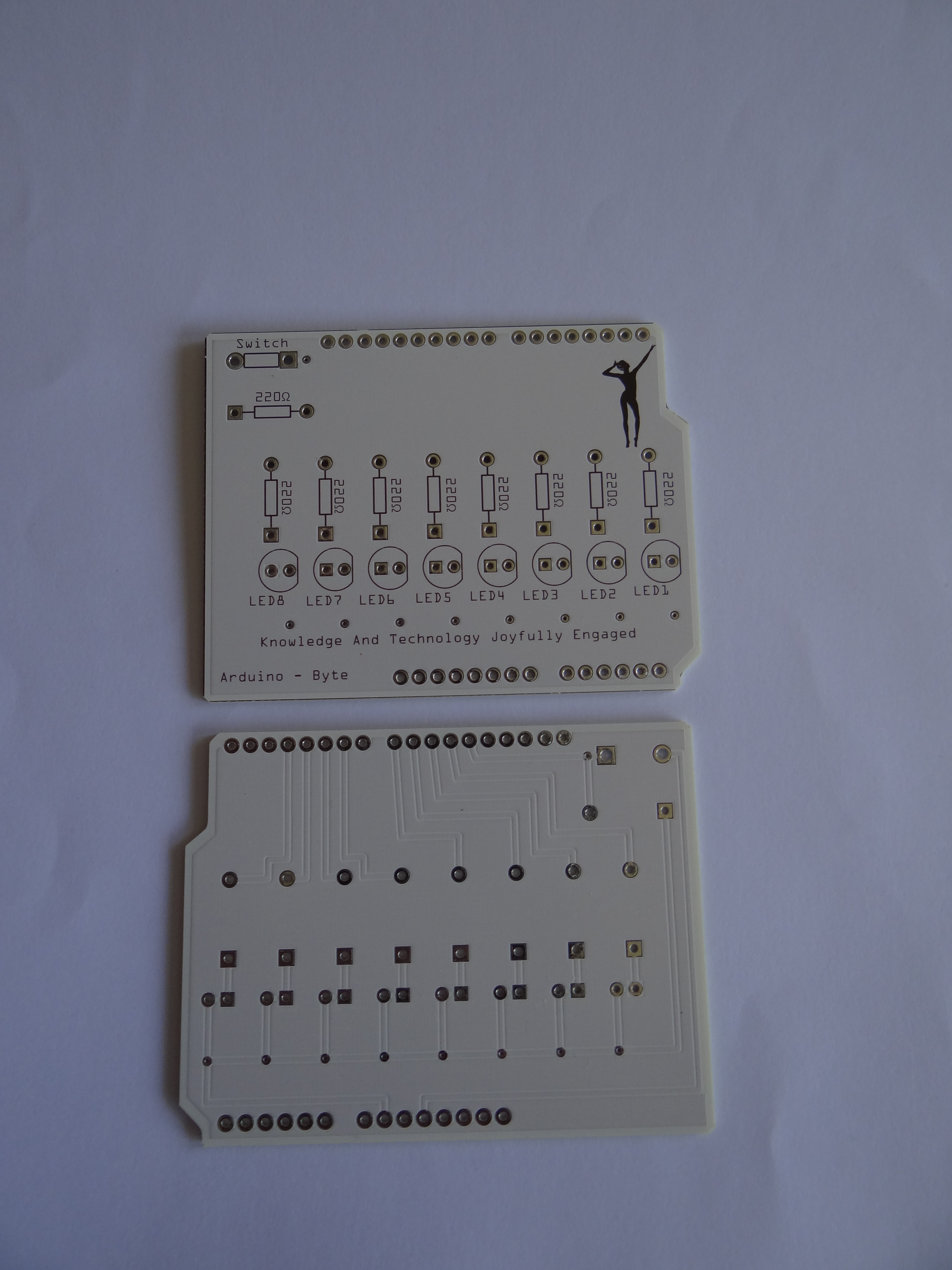
In the above picture you’ll see two round boards, two rectangle boards and two square boards. These are some boards that I’ve been working on.

The rectangular board supports an 74HC165 IC, which is an input shift register. I have a similar board for an output shift register. Basically, the 165 reads voltages (High or Low) from 8 pins to translate them to bits in a byte. The 595 translates bits in a byte back to voltages. Having this on a special board is just practical.

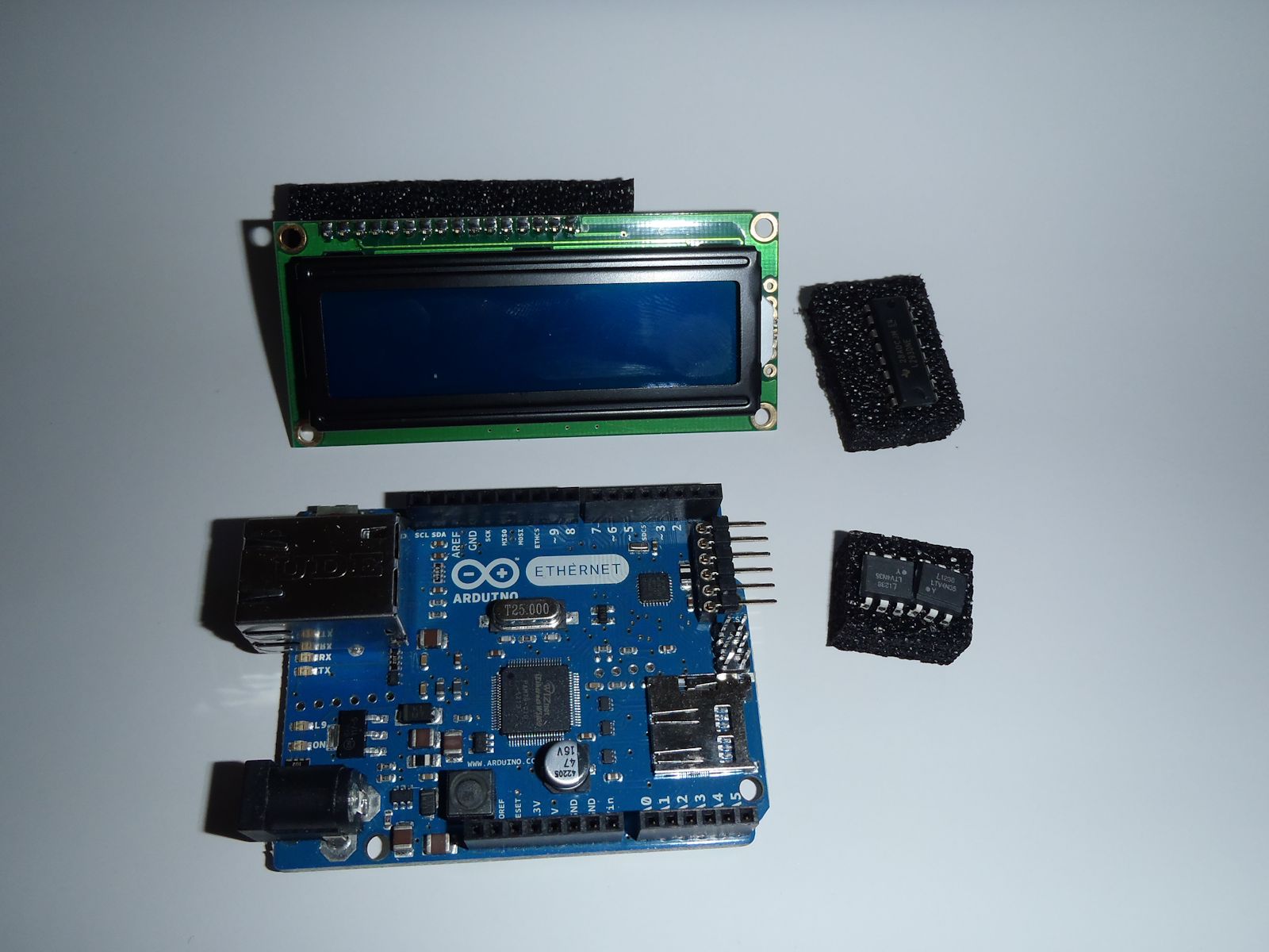
The square board combines the 74HC595 shift register with an ATTiny processor, which is linked again to an ESP8266 module. (The ESP-01.) This basically makes a multi-processing board where the ATTiny can handle various LEDs while the ESP sends commands to the ATTiny based on input from the Internet. And the ESP still has 3 pins available for other input or output. But this board is for a later post…

It’s the round board that matters, though. This is what you need to roll two dice. And it has three major parts. The first part is the design of the board. The second part is choice of hardware. The third part is the code to roll dice.

Design

Two dice, by W.A. ten Brink.

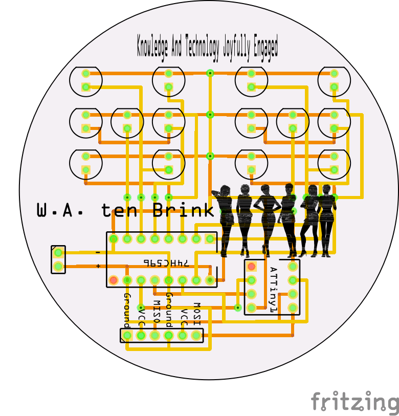
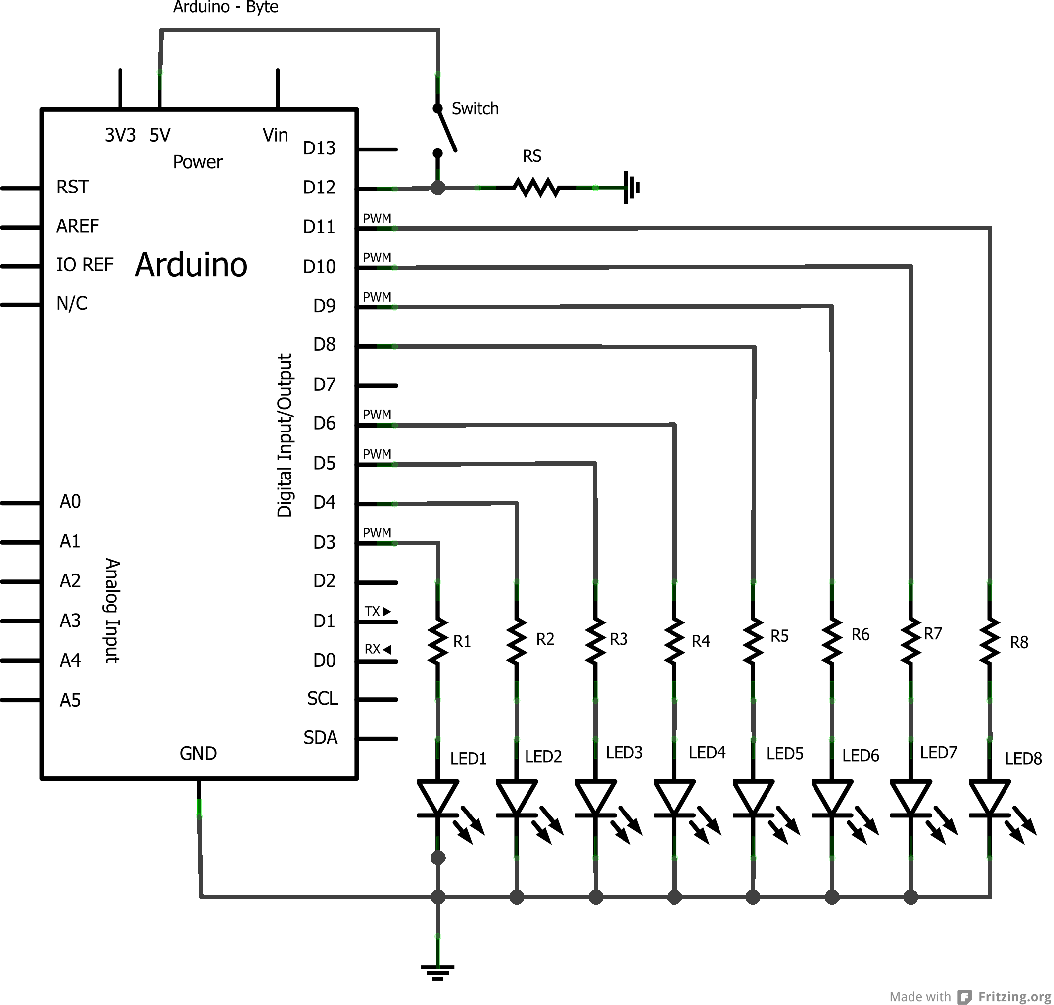
Well, the design is reasonably simple. Power is on the left and the yellow lines are on the top while the orange lines are on the bottom. The 74HC595 has 4 pins per die so with 8 pins I can handle 2 dice. If I want more dice then I would need to chain more of these 595 IC’s. On the right is the 8-pin ATTiny and pins 0 and 1 go to the bottom, allowing communications with “something else”. Three other pins are needed to control the 595. And then there are 14 LEDs consisting of 6 pairs and 2 loose LEDs, resulting in just 4 combinations for every die. Which is exactly what I need.

Hardware

Now, for the hardware I have many options. For my first board, I decided to use an ATTiny13 as this processor is very limited in it’s options. It only has a kilobyte of RAM! And in a time where computers have lots of gigabytes of RAM, a single kilobyte is just unimaginable. It’s slightly more than a thousand characters so this post is likely to be bigger than this RAM can handle. But to roll dice, you don’t need much code…

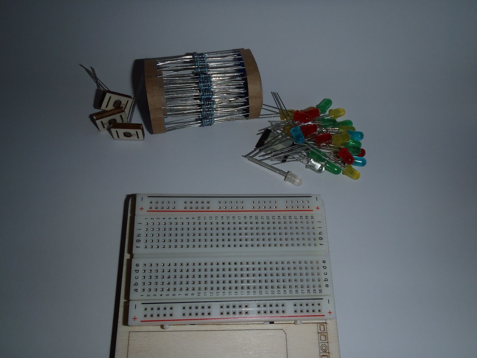
For the LEDs I’ve picked purple-UV LEDs just for fun. These are pretty clear in the day yet not too bright. And in the dark they provide a blacklight-effect. I did not add any resistors as the whole setup doesn’t use that much power to begin with. These LEDs can handle the voltage.

As for input, I decided to add two capacitive buttons. These will already respond when your finger is near the button so you don’t have to touch them. Which is interesting as I’m planning to cast the LEDs and buttons in resin to give it a smooth surface.

Code

And then the code for all of this. I still needed 105 lines of code but that’s mostly because I use a lot of ‘define’ statements and added several comments. This is the code:

#define CLEARLEFT 0b11110000
#define CLEARRIGHT 0b00001111

#define LEFT_2  0b00000001 // LB-RT
#define LEFT_3  0b00000010 // Horizontal
#define LEFT_4  0b00000100 // RB-LT
#define LEFT_1  0b00001000 // Center
#define RIGHT_2 0b00010000 // LB-RT
#define RIGHT_3 0b00100000 // Horizontal
#define RIGHT_4 0b01000000 // RB-LT
#define RIGHT_1 0b10000000 // Center

#define ROLL_L1 LEFT_1
#define ROLL_L2 LEFT_2
#define ROLL_L3 LEFT_1 | LEFT_2
#define ROLL_L4 LEFT_2 | LEFT_4
#define ROLL_L5 LEFT_1 | LEFT_2 | LEFT_4
#define ROLL_L6 LEFT_2 | LEFT_3 | LEFT_4

#define ROLL_R1 RIGHT_1
#define ROLL_R2 RIGHT_2
#define ROLL_R3 RIGHT_1 | RIGHT_2
#define ROLL_R4 RIGHT_2 | RIGHT_4
#define ROLL_R5 RIGHT_1 | RIGHT_2 | RIGHT_4
#define ROLL_R6 RIGHT_2 | RIGHT_3 | RIGHT_4

// Value of (last) roll.
int left = 0;
int right = 0;
// Pin for left button.
int leftPin = 0;
// Pin for right button
int rightPin = 1;
//Pin connected to data pin of 74HC595
int dataPin = 2;
//Pin connected to clock of 74HC595
int clockPin = 3;
//Pin connected to latch pin of 74HC595
int latchPin = 4;

int LeftValue(int value) {
  switch (value) {
    case 1: return ROLL_L1;
    case 2: return ROLL_L2;
    case 3: return ROLL_L3;
    case 4: return ROLL_L4;
    case 5: return ROLL_L5;
    case 6: return ROLL_L6;
  }
  return 0;
}

int RightValue(int value) {
  switch (value) {
    case 1: return ROLL_R1;
    case 2: return ROLL_R2;
    case 3: return ROLL_R3;
    case 4: return ROLL_R4;
    case 5: return ROLL_R5;
    case 6: return ROLL_R6;
  }
  return 0;
}

void WriteDice() {
  int lastRollValue = 0;
  if (left > 0 && left < 7) lastRollValue = (lastRollValue & CLEARLEFT) | LeftValue(left);
  if (right > 0 && right < 7) lastRollValue = (lastRollValue & CLEARRIGHT) | RightValue(right);
  // Avoid flickering LEDs, disable LEDs.
  digitalWrite(latchPin, LOW);
  // Send out the byte value.
  shiftOut(dataPin, clockPin, MSBFIRST, lastRollValue);
  // Avoid flickering LEDs, enable LEDS.
  digitalWrite(latchPin, HIGH);
}

void setup() {
  randomSeed(millis());
  pinMode(dataPin, OUTPUT);
  pinMode(latchPin, OUTPUT);
  pinMode(clockPin, OUTPUT);
  digitalWrite(latchPin, HIGH);
  for (left = 1; left <= 6; left++) {
    for (right = 1; right <= 6; right++) {
      WriteDice();
      delay(10);
    }
  }
  left = 1;
  right = 1;
  WriteDice();
}

int Roll() {
  return random(1, 7);
}

void loop() {
  // Check if we're pressing a button. If so, update time!
  if (digitalRead(leftPin) == HIGH) left = Roll();
  if (digitalRead(rightPin) == HIGH) right = Roll();
  // Display the rolled results.
  WriteDice();
  delay(50);
}

I start by defining the left and right sides. Left are the 4 bits on the right and right are the 4 bits on the left. Meh. I should have thought about that before…

I then define the four channels that each die has. These four channels per die allow me to define the combinations needed to display the values 1 through 6.

All these defines will translate to hardcoded values so that saves a few bytes in variables. But I do need a few global variables, though. I need variables for the pins and I need variables to remember the values of the left and right die. Well, I could have used “define” for the pin values but I seem to prefer to use variables for pins. Not sure why, exactly.

Two functions called LeftValue() and RightValue() are used to translate a number between 1 and 6 to the proper bit-pattern. All other values will result in 0.

The WriteDice() function will handle sending the dice values to the LEDs using the 595. It’s not too complex. Calculate the proper byte value to hold both dice and then send it to the 595. (Turning off the latch so it won’t flicker.)

The setup() function is also a simple one, but I want to show the dice are working during start-up. That’s why I loop through all possible combinations before displaying snake-eyes.

A simple Roll() method returns random values between 1 and 6 so that’s where dice are rolled.

The Loop() function is just checking if any of the input pins is getting a signal. If the voltage is high, it will roll for that die. If low then the old value remains. As this is inside a loop, it will just keep rolling for as long as the voltage is high.

I used touch buttons as input so as long as you keep your finger on it or close above it, it will just keep rolling. Which gives an interesting effect. This is done on purpose, allowing a player to “shake” the dice for a while. But instead of these buttons I could also have chosen another form of input. Even more interesting, I could have set up serial communication over these two pins with another board, allowing a secondary device to control the rolls.

So, I could attack an ESP-01 to it and let the rolls be made over WiFi, sending the results back to some web server. This is where my other board with the ESP-01 and the ATTiny could be used.

Conclusion

It is a bit challenging to come up with a simple idea like this. Especially when you’re still not very experienced in electronics. The use of the ATTiny13 was very challenging because it is so limited in memory. The ATTiny85 has 8 kilobytes of RAM, which is more practical. Still not a lot, but enough for many simple purposes.

The whole device works on a 3.6 volts battery but I want to cast the whole thing into opaque resin just to make it look more interesting. But I’m also considering making another one that is connected to an ESP-01 so it has WiFi capabilities. (The IC’s and ESP won’t be cast inside the resin, though!)

Once it’s finished I should be able to connect it to a battery or USB port or some other power source, which will make sure the voltage doesn’t exceed the 3.6 volts.

The use of raw ATTiny processors is very interesting because of it’s limitations. For a software developer, these IC’s are really interesting as you need to optimise for size, while keeping speed high. You’re thinking more in clock cycles and bits. It’s a huge difference compared to designing a whole website with database backend where the amount of executables is easily megabytes in size while data can exceed gigabytes of disk space. Good developers can think small and big.

Four models on Shapeways (NSFW)

I like Shapeways since you can upload your own 3D designs and end up with a 3D printed model. This allows me to e.g. create custom boxes for small hardware experiments. These boxes are combined with my Poser models and will thus result in very interesting designs. But like everything with 3D, you will have to do some experiments first. I created three new models in Poser named Nora, Tommi and Cassiopa and I used some interesting trick to create a special rack to include in the pose. But first, let’s look at Nora:

WIN_20151026_102324 WIN_20151026_102455

Nora was printed in two versions: White plastic and Colored sandstone. And in both models a few flaws were already visible. Nora’s shoes were made of a very thin material and the upload to Shapeways did a repair that removed the very thin parts. As a result, the shoes are flawed.

WIN_20151026_102331 WIN_20151026_102500

Well, a bit of glue and plastic can fix that. But her fingers were also a bit delicate and the sandstone version ended up with broken fingers because the fingers are actually too thin. Again, some glue and they’re back in place.

WIN_20151026_102352 WIN_20151026_102505

Her thumb is still missing, though. Then again, I was more interested in checking how well the 3D printer handles holes, like the area where she keeps her left hand. In front of her genitals, to keep it decent, yet far away so it doesn’t touch. Combined with the position of her legs, this results in a complex hole to print but it ended up flawless. Even her left hand was intact.

WIN_20151026_102409 WIN_20151026_102511

So, what I’ve learned from Nora is that thin elements like fingers and shoes won’t print very well. White plastic does a better job than sandstone, though. That’s because sandstone needs further processing after the printing is done, which requires some manual labour. Thus, small parts can end up being damaged.

Another part that’s important with the sandstone version is the textures. For this, I will check her face:

WIN_20151026_102344 WIN_20151026_102524

And in case you’re wondering why her hair is covered by a towel, well… Hair really doesn’t print very well. It tends to generate loose shells or often to parts that are too thin to print. Besides, the towel makes her look as if she’s just out of bath, relaxing.

The White plastic versions shows a reasonable amount of details in her face. Even her open mouth is printed quite nicely. The sandstone model also has an open mouth and you might see her tongue and teeth if you look inside with a microscope. But I’m more looking at her face and eyes.

Printing in colored sandstone has an ink density of about 50 DPI. Normally, a printer would print at 300 DPI so the colors will lose details. But I chose a light-colored iris and Nora has good-looking pupils in this print. Which is important to remember, since dark eye colors might darken the whole eye. It still looks good in my opinion. At least better than what I can do with paint and a brush.


The next model is Cassiopa. Since I know that thin parts won’t print well, I’ve placed her on a towel, hoping for a better result. The result is okay but the sandstone version did not survive the print because the towel was too thin. So I uploaded a newer version of Cassiopa on a more solid floor and in this version, I also adjusted her clothing. Why? Because I need to test more than just panties on topless women. Still, the white plastic version looks okay, although it is a bit small:

WIN_20151026_102632 WIN_20151026_102652 WIN_20151026_102700 WIN_20151026_102817

The model was almost 15 CM long, but that’s the length of the towel. Cassiopa uses only 2/3rd of this length, thus she’s smaller than my other models. (This also happens with one of my Tommi models.) Smaller means that fewer details will be visible but it is still detailed enough.

The towel she’s on has a hole in it, which is too bad but I’m not too worried about it. I now know that I can’t use these kinds of thin plateaus for my models to rest upon. In the sandstone version, the towel had crumbled away.


The last model is Tommi which I’ve combined with a rack. I made a second version of Tommi climbing this rack but Tommi herself becomes small if you do this, thus losing details. Let’s look at the climbing version first:

WIN_20151026_103142 WIN_20151026_103151 WIN_20151026_103216 WIN_20151026_103233 WIN_20151026_103242 WIN_20151026_103256

I gave Tommi a skirt instead of panties so you should have been able to look up her skirt. However, Shapeways repairs this automatically and as a result, the skirt became solid. And that’s a flaw in the skirt model.

This is a colored print so her texture helps to add details, but she’s too small to be very clear in details. She did have a flaw in her right hand, since her fingers were too thin and either did not get printed or broke off afterwards. A bit of paint will fix that, though. It is just something to remember.

So, remember: make sure thin parts are well-supported and preferably resting against something else and with clothes, be aware that Shapeways might fill in specific areas that you’ve hoped would stay hollow. In this case her skirt but I also tried another interesting top on Tommi but that added a white mass over her breasts since Shapeways was filling the area between the left and right cup.

Next, the bigger version of Tommi with her resting upon the rack. That one was perfect, although one of the legs from the rack had broken off during transport. So, even if a part is thick enough to print, it might still be very vulnerable. With a length of over 4 CM, they can’t handle a lot of stress. Still, this model is great with no broken appendices and even her toenails are visible!

WIN_20151026_102904 WIN_20151026_102914 WIN_20151026_102958 WIN_20151026_103102

Well, at least I glued the leg back in place. I might decide to remove all four instead, though, if I fear they will break again. This model happens to be quite heavy too, which makes sense since she has the biggest volume of all. Her eyes are nicely detailed and her skin color even has some variation around her knees. And you can see her toenails! A bigger model is nice in that regard so if your model has a lot of fine details, have it printed in a larger scale! Although the price will scale up too, since more materials will be required.

Well, these three models all look reasonable well and taught me what I need to know about printing Poser models: use a reasonable large-scale, support all small parts and be aware that hollow spaces might end up being filled with extra material because Shapeways “repairs” some thin materials.

I kept these models mostly undressed because I know the textures of these models and needed to see how the color printing will support the texture details. Also, it is difficult to find Poser clothing models that are working well when uploaded to Shapeways. These models are not made to be printed in 3D but to be rendered. So finding good clothes to print is difficult. For Victoria 4, her bikini top and bottom do print quite well, though. They too are filled up, but the filling it towards the body of the model and not between both cups.

Another problem is the limitations on models set by Shapeways. There’s a size limit and there’s a polygon limit. (64 MB or 1 million polygons.) Poser models can easily go over this amount of polygons so you will have to find a way to reduce those, while keeping textures intact.


And then there’s the rack used by both models. The rack is the same length for both and I’ve created it myself by using the Firestorm viewer with the Second Life virtual worlds, but I could have used my own OpenSim world too. I just joined several cylinders for the rounded sides and balls for the rounded corners to build the framework. I also created a square plane with a hole inside, which I copied three times and put next to one another. I then exported the whole model from the SL viewer to a Collada file, which I imported in AccuTrans 3D to clean it up a bit and to reduce the complexity of it. (For example, by merging all parts into one single part.)

And then I checked if the rack has enough space for other hardware.

WIN_20151026_104131 WIN_20151026_104323

Well, the rack isn’t wide enough for an Arduino board

Since I copied the square plane three times, I had expected all holes to have the same size. And the rack was made so I can add some hardware in the empty rack space and have some wires or other parts move through the open holes to e.g. shine a LED light on the model. So, I was surprised when I discovered that the middle hole was slightly bigger than the other two. Which I discovered by trying to fit an Arduino-board. (The YUN is shown in the picture.) The length is long enough for the Arduino Mega but it will have a few millimeters on the sides of the rack. The pins are actually at the exact location of the long bars. So you could actually put an Arduino in the rack if you don’t mind the width.

But smaller devices like the Arduino Mini, the Trinket, the NetDuino mini and the Digispark have plenty of room inside the rack.

But back to the holes!

WIN_20151026_103544WIN_20151026_103535 WIN_20151026_103705 WIN_20151026_103853 WIN_20151026_103920 WIN_20151026_104434

Using the climbing Tommi version, I used to try a green LED. It doesn’t fit the top or bottom hole but it does fit the middle hole. Trying it again with a regular lamp of 5 MM diameter, I see it going through the middle hole without effort but the top and bottom ones don’t fit. A laser light won’t even fit the middle hole, though.

The conclusion is that these holes are a bit too small for LED lights. No problem, since I can take a drill bit and make them wider. Still, I had hoped they would be big enough for a LED light. So I have to redo my calculations. And I have to wonder why the middle hole is bigger than the other two, while they’re basically all the same in my 3D software.

Anyway, I now have two great models for containing some of my experimental hardware. I know the racks are open so the hardware would be exposed but that’s something I will solve with a next version of my rack. I also know how thin the walls can be and how thin the walls of my rack are. I can still have the rounded areas but the rack should get more solid walls. Thin walls too, since the rack has a lot of volume.

Next, the question what I would like to create with these models. Whatever I think of should match the model. The three holes in the rack are meant for lights, cables, buttons or something else but I don’t want to show too much hardware on the model side of the rack. I also need to find a solution to attach the additional hardware to the rack, since it doesn’t have any special pins or whatever to hold them. Then again, these models were created to see how well these racks would print. The different hole size was a surprise for me which I need to include in my calculations.

And the three rack-less models? They’re just nice desk ornaments.I have ordered more prints so I will likely have more ornaments soon.

My next designs will have better racks, preferably with extra points to hold my hardware in place. The sandstone prints still look great but I have to consider the size of the whole thing. And I will need to experiment with clothing, to see which items will print best. The same is true with hair, since I still have to find hair that prints well in 3D.

All in all, 3D printing is a very interesting challenge. Slightly expensive too, though.

Just a Byte…

I recently started with the Arduino hardware and decided that I needed to create something electronic to command from this specific hardware. Since I am a software geek, I immediately came up with the idea to visualize a byte by using 8 LEDs. I also wanted a simple switch in the design so I could give it some special function, although a single switch isn’t offering very much functionality. So the first design used a broadboard and lots of cables to connect it all and looks something like this:

Byte_bbYeah, that’s a lot of cables. And 8 LEDs, 9 resistors and a switch. It’s nothing spectacular, though. But this design does need to use 9 pins from my Arduino board, making it a bit pin-hungry. You might want to prefer to have all communication to go through a single pin, plus two more for ground and power. But I decided that I just need an experimental thing that would use several pins.

When you look at its schematics, it looks like this:

Byte_schemAnd now, weeks after creating this design, I still wonder why I added a resistor between the switch, pin 12 and ground. Then again, if I would use pin 12 as an analog input, I would not just get a signal when someone presses the button, but also a very low signal related to the number of LEDs that are burning. That’s an interesting concept but I still have to test it.

However, this setup isn’t very practical. All those wires, the LEDs that are a bit loose within the board and the switch that didn’t really want to stay in place made it a bit complex to handle. So I decided to use their services to create a Printed Circuit Board. It would some time for them to fabricate it, though. But still, it would be neat to have some board that I can just click on top of my Arduino.

So, recently I received four of these in my mailbox:

PCBInteresting effect: while the text, logo and instructions are in the front, the actual connections are on the back of this PCB. Did I do this on purpose? No, not really, but I like the effect. It makes the front very smooth, making it even prettier to show. And the logo in the shape of a woman stretching her arms serves the same purpose. Just there to make it look more interesting.

The next step was to add all the LEDs, resistors, the switch and the connecting pins to the PCB. That took some patience with soldiering but I’m happy to say it was a success:

BitsAnd yes, the BytePanel code for this project was also quite easy to write, although C/C++ isn’t really my speciality. (I prefer C# or Delphi/Pascal, although I have plenty of experiences with lots of other languages.)

To get this panel to work, I needed a simple piece of code that would set or reset the specific pins that are assigned to the LEDs. And I need input from one pin to detect if the user presses a button. But to make things more practical, I would need a special class for this whole thing. So it was time to write a whole C++ class including header.

class BytePanel
{
  public:
    BytePanel();
    boolean isPressed(); 
    void reset(); 
    void loopBits(); 
    void loopBitsReverse();
    int next(); 
    int previous();
    void set(byte value); 
    void setValue(int bit, boolean value);
  private: 
    // The current value
    byte currentValue;
    // The pins
    int pins[8];
    // The bit masks
    int masks[8];
    // The switchpin
    int switchpin;
    void update(); 
};

This class would need a constructor with the intelligence to set all used pins to either input or output. It would also need to initialize all variables used, including the counter value which remembers the value of this byte.

Next, it would need a simple function to either set or reset a specific LED. This is what setValue is supposed to do. This method is called a few times, since any method that sets or resets bits will need to call this method for every bit.

The function set is a bit more practical, since it accepts a byte value and sets the LEDs to this specific value. However, it will not influence the current value that it stores internally. I could add this but I feel it would give too much functionality to this simple method. Besides, if I want to be able to set any value to the current value then I would need to create a property to get/set the value, instead of keeping it read-only.

Then a few methods called nextprevious and reset that will display either the next value, the previous value or reset this counter to 0, which means no LED will be burning. They all call the update method which is used to display the current value. Which is practical if you’ve used the set method to override the value.

Two methods called loopBits and loopBitsReverse will just flash each led for 20 milliseconds. The first method goes from low to high and the other from high to low. These are just fine to call when you start the device, so the user gets a visual sign that the device is working.

This class actually makes it quite easy to use the button to increase the byte value. When the device starts, I just loop the bits before resetting the byte. Then, when the user presses the button I will call the next method to move to the next value. However, I also want to reset the byte, and decided that I need to press the button for half a second before it would reset. And to make things complex, the byte should not increase for as long as I keep pressing the button.

Well, this wasn’t that complex after all:

// Now wait for up to half a second.
 int count=50;
 while(count>0){
   delay(10);
   // Did user release the button again?
   if(!panel.isPressed()) break;
   count--;
 }
 // If count is 0 then the user wanted to do a reset.
 if((count==0)) {
   // Reset the byte.
   panel.reset();
   // Wait for user to release the button.
   while (panel.isPressed())
   {
     delay(10);
   }; 
 }

Basically, when the button is pressed, I increase the byte. I then enter a loop that will break if the button is released, or else end when it has counted 50 x 10 milliseconds. In the latter case, the counter will have reached zero, thus I need to reset the byte. I also need to wait for the user to release the button again, else the counter will start at one, not zero. (Because the button is pressed when it iterates from the start again.)

It’s not very complicated to do, as you can see. And of course I could add even more functionality. For example, if the user presses the button for half a second, it should light all LEDs and then move in reverse order, thus every new press of the button would call previous to decrease. Press it for half a second again and it will move forward again. And press it for a full second and it will reset itself.

It’s just one button so I can’t add much functionality to it anyways. But I’m still proud of my first Arduino project. It’s small and it looks nice. I can connect just a battery to it, like in the picture, then press the button to show a specific 8-bit value in binary. And… Well, that’s all, actually. 🙂

But what’s more important: I now have a piece of electronics which I can use to write software for! For example, I could use a serial connection to send bytes from the computer to display as bits on this device. Maybe even make it communicate with a second Arduino device so one will send values that the other will display.

And I have three more PCB’s that I can use to create three more of these simple devices. 

The Arduino and the Raspberry Pi.

As you might know, I’m a software engineer. Senior, even. Creating software isn’t just my daily work, it’s also my most favorite hobby, and I invest a lot in my own personal knowledge. I’ve been using a legal Delphi version since 1995 when Delphi 1 was marketed. Before that, I owned a Borland Pascal 7 compiler, allowing me to write both MS-DOS and Windows applications. (End before that, I owned Turbo Pascal 6.) The same with Visual Studio, which I owned myself since the first .NET version was sold. I did skip version 2005, but purchased the 2008, 2010 and the latest 2012 versions, just to keep up with the latest techniques. I also have a license for SQL Server Developer and I use Altova’s Mission kit on a regular basis too to create XML schema’s and to process XML files by using style sheets.

But all this is just working inside the box. You do something on the computer and when people ask me what I do, I have to turn on my computer or laptop, start whatever I’ve created that I can show and once the demonstration is done, I can close it all up again. And after many years, I’ve decided that I need to work “outside the box” too! I need something I can show without the need of my computer, but it should still work together with my computer. And thus I arrived at the Arduino and the Raspberry Pi.

So, let’s start with the Raspberry Pi:

OLYMPUS DIGITAL CAMERA

Basically, it’s just a mini-computer which you can use to run Linux. And by using Linux, you could create all kinds of applications by programming them in C++, Python, PHP or any other development system that is available for Linux, and which can be ported to the Raspberry Pi. (Because it uses an ARM processor, which you can also use for mobile phones and cheap tablets.)

But when you look at the little board above, you will notice it has a bunch of pins available, which you can use to connect all kinds of hardware to this little board. And no, it already has a port for USB devices and a HDMI connector and even has a SD card reader so that’s not the kind of hardware that you need to connect. So, what kind of hardware can you connect?

Actually, anything you like! But you will have to be aware of the programming to send signals to the connected hardware and make sure you use the right voltages, else your hardware might burn up. You could, for example, connect a LED light to two of the pins and send a signal to one of those pins every second for half a second. You would then end up with a flashing light.

However, the 3.3 volts the Arduino provides is a bit much for a LED light so chances are that it will break with a final flash. So you need to take more precautions and add a resistor to the setup to lower the voltage. And maybe you want to do more than just create a flashing light. You could add a switch button to turn it on and off manually. Or maybe add a light sensor so it only turns on when it gets dark. Maybe you want to create a warning signal, telling you when your computer overheat by adding a thermometer circuit to your setup. And maybe add a motor and some wheels so your computer can drive around.

But to do all that, you would need something to create your electronics on. A printboard would be nice, but would require soldering, thus you can’t re-use any parts once you’ve used them. Thus you could use software like Fritzing to first create your electronic designs, which you can then put on a broadboard with all more components:

OLYMPUS DIGITAL CAMERA

yeah, that’s plug&play. 🙂 On the top left you see three light sensors. Next to it a bunch of resistors and a collection of LED lights. On the bottom the broadboard which you can use to plug them all together. And you’ll probably want a bunch of other electronic parts like condensators, wires, buttons and a lot more. All inexpensive parts that you can buy in the average electronics store. (And often used with model trains…)

So, you can use the Raspberry Pi to create your own light system, but isn’t it a bit overkill to use a whole computer just to switch on a light? Yeah, sure. Which is why the Arduino board happens to be a nice, and less expensive alternative:

OLYMPUS DIGITAL CAMERA

On the right you’ll see the Arduino Uno, which is a programmable board with just a little memory and a bunch of holes that you can use to connect your hardware. The Raspberry Pi has pins, but the Arduino has holes, which makes it easier to plug in wires.

On the left, a special Ethernet shield, which happens to have lots of pins in the bottom to connect to the Arduino board. It’s basically an extension to connect your Arduino to the Internet, so it could, for example, send or receive commands from any computer. And this is what makes the whole device very interesting! You can “talk” to it over an Internet connection.

However, to make the shield and board work together, it needs to use some of the pins that you might want to use for your own experiments instead. So there’s an Arduino board with a build-in ethernet connection:

OLYMPUS DIGITAL CAMERA

And yes, above the board you’ll see a LCD screen that you could use to display messages. You also see an IC that can be used for some simple processing of your signals that you’ll be sending over the wires. And two optocouplers that can be used to isolate two systems with different voltages, yet allowing signals to be sent between them.

The Ethernet board does lack a USB connection, though. Then again, if you want to create your own internet-enabled electronic device then this is just more than enough as the foundation of your project.

There are also several other types of Arduino boards, each with their own special properties. I don’t have those yet, though.

The Arduino is very useful for projects that don’t need a lot of coding. Otherwise, the Raspberry Pi would be a better solution. The Raspberry Pi can, for example, be used as a web server, allowing you to send much more complex signals than the Arduino can handle. Plus, you can connect a monitor, keyboard, mouse, hard disk and other devices to your setup, like this interesting monitor:

OLYMPUS DIGITAL CAMERAAnd yes, it could be possible to use this monitor from an Arduino board but the amount of programming you’d need would be huge, and the amount of memory the Arduino has would not allow you to do something complicated. So, if you want to create a photo frame with a special remote, the Raspberry Pi would be more practical. If you want to set the lights on your model train station based on the amount of light outside, the Arduino would be better.

The Arduino has another advantage, although the Raspberry could make use of that option too. The Fritzing software allows you to design something and show what it would look like on a board. Say, for example, that I want to manage eight LED lights by using a switch. For example, a binary counter which displays it’s current value as a byte value. As an electronic schema it would look something like this:Byte_schema

In the above schema I use nine pins from the Arduino to handle all lights and the switch. And yes, I could have used just one if I added an IC and some additional components but I want to keep this extremely simple. Besides, using an IC means that I would have to use serial communication between the Arduino and the board, while I want this project to do things parallel.

But above schema is interesting but you might want to build it so you can test if it works. You should also build it so you can test the code for the Arduino which should do some action based on pressing the button. This has not been defined by me so I could use this all, for example, with an Ethernet board and have a computer send or receive a byte value to the board when I press the button. 

Anyways, the Fritzing software can display me what the board would like, although I did show all wires reasonably neat around the board:

Byte_bb

But once my design is finished, I don’t want to lock up my broadboard just for this project. I might want to create another thing next, thus I would need my board and my components. So, the solution would be to have a circuit board printer for just this project, which would look something like this:
Byte_pcb

A simple design, which fits a single side of a board, allowing me to add the components that I used on the broadboard before. A bit of soldering, adding a few pins to connect it to the Arduino board and I would end up with an interesting device, which still needs some code to operate the lights. But hey, this is the hardware side, allowing me to show something outside the box!

The next step would be writing the code for the Arduino itself, which should turn on or off some of the lights based on certain conditions. And it must respond to a button press. But what this project is going to be, I don’t know yet. A connection with a web server, having some kind of communication between my board and the web server would be something interesting to show. It would allow me to go back to the box, design something and then show the result on my Arduino board, which could be build in some black box with just the LED lights and the switch visible.

Too bad it would still need a cable to my router, but there are possible alternatives. For example, there’s also a WiFi-based option, or something with Bluetooth. Or perhaps even with a GPS module and then sending SMS messages. There are a lot of options for me to work outside the box with just these components!

By the way, since the Raspberry Pi has a build-in USB connector, I could just use a WiFi USB dongle instead of the Internet cable to make it a wireless device…