Print your own cases, part 5 of 10

In the previous post I created a Poser model and a few OpenSCAD models and joined them into one. But before I continue to manipulate them to make them ready for 3D printing, I wanted to do an artistic rendering of the model, just to show off! This means that I want a complete background with water, trees and other stuff and the model in the middle of it all, well-lit and looking cool.

While it might seem a waste of time, it does give one extra view on your model before you continue processing. It will look okay but the OpenSCAD objects will not have any color. Problem is that painting those object cannot be done in Poser or OpenSCAD so if you want a specific coloring of those objects, you will need a special tool to do so.

2016-04-19 (4)

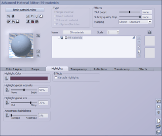
Modeling in Vue is quite easy. You just import the Poser model and then you put it where you want it to be. But once imported, you should turn down the highlights of the Poser model, else it starts to shine, which isn’t pretty. So, select the complete Poser model in Vue and click “Edit all materials” to change the highlights. 

Vue now has a value of 50% for my model. This is actually the highlight of one part of your model and not all parts! But if you change this value, it will change it for all.

2016-04-19 (6)

Since it has the value of 50%, I can simply overwrite it with 0. If it had been 0, I would have chosen the value of 1 instead.

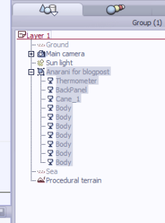
I have already removed the ruler from the list of parts in Vue and I can easily find the other pieces that I’ve created because of their names. Unfortunately, Poser tends to name all figures “body” while all properties keep their old name. And that’s a bit annoying.

Often I will rename those parts but this will just be a quick render so, skip it.

Since I lack the tools to paint the OpenSCAD models, I will just pick a few from the materials that Vue already has. I decide to pick grass for the back panel because it always looks good to have a model walking on grass. And I pick dark smoked glass for the box. The cane will be gold, making it shine.

Next, I check the materials that are provided by Poser. The dress, for example, has a zipper which uses a reflection map. I hate those, because Vue does a full 360-degree view of everything if I want to. Reflection maps are a poor alternative for real reflections.

2016-04-19 (7)

I also decided to change the color of her bra. This won’t replace the texture but just the color. And I decide to pick an orange trim and green cloth, both pastel-tints.

2016-04-19 (8)

I also decide to put the sun in the background to create a kind of ‘eye in the sky’ so I also need a second light, which I put at the location of the camera. To get it there, I just select the camera, which will put it in the center of the views. When you add lights or objects, they will be put at the same place. Thus, the light is at the location of the camera!

And a quick preview of the image shows me that it will look good. So let the rendering start!

Now, one reason I use Vue to create an artistic image is because it allows me to use a transparent material for some of the more complex objects. In this case, that would be the box with its round shape. With the image rendered at a large resolution I can check the box for possible flaws, if I want to use it again with another model.

In my next post I will show how I clean the model using Accutrans 3D. In the mean time, this is what the rendered artwork looks like:

Anarani for blogpost

Print your own cases, part 4 of 10

In my previous post I created a round container for my electronic thermometer and now I need to add it to my Poser model. But I also need a special stand for Anarani to stand upon, with a back panel for a couple of magnets. Lets immediately start with the OpenSCAD script:

$fn=250;
difference(){
  union(){
    cube([60, 60, 6]); 
    translate([28, 0, 0]) cube([4, 3, 160]);
    translate([20, 1, 10]) cube([20, 2, 20]);
    translate([10, 1, 140]) cube([40, 2, 20]);
    translate([30, 1, 20]) rotate([90, 0, 0]) cylinder(d=12, h=1);
    translate([20, 1, 151]) rotate([90, 0, 0]) cylinder(d=12, h=1);
    translate([40, 1, 151]) rotate([90, 0, 0]) cylinder(d=12, h=1);
  }
  union(){
    translate([3, 3, 2]) cube([54, 54, 5]);
    translate([30, 1, 20]) rotate([90, 0, 0]) cylinder(d=10, h=2);
    translate([20, 1, 151]) rotate([90, 0, 0]) cylinder(d=10, h=2);
    translate([40, 1, 151]) rotate([90, 0, 0]) cylinder(d=10, h=2);
    translate([30, 2, 150])
    rotate([270, 180, 0]) height = 2) {
      text("Anarani", 
      size = 7, 
      font = "Harlow Solid Italic", 
      halign = "center", 
      valign = "center"
      );
    }
  }
}

This isn’t very special. A floor plate with an edge and a pole with two plates which will hold the magnets. As you may notice, there is no connection to the box that I created in the earlier post. That connector will be something from Poser. All you have to do now is to convert these models to WaveFront .obj files and you can import them in Poser. So, let’s combine them with Anarani! And this will show a few issues with importing in Poser.

2016-04-19
Anarani for blogpost II_0001

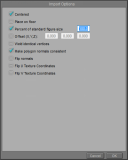
When you do import models in Poser, prefer to enable “Percent of standard figure size”. The reason for this is that the standard figure size is extremely small, compared to the imported objects. I will scale them anyways once they are imported and because their size is relative to Anarani, I can use integer values between 1 and 100 to scale them. Otherwise, I would need to scale them to very small numbers with fractions.

Now, to do a proper scaling, I will use the ruler to measure the height of the opening in the temperature holder, which should be 46 mm. I will then use the ruler to scale the back panel to the proper size, thus having it synchronized with the size of the box.

You could wonder why I don’t combine all three parts into one .obj file and import that one, but when I do that, it becomes just a single part. And I need to move them around, so that isn’t very practical.

So I end up with my model looking like the image on the right. The temperature box is too big and the ruler is extremely small. The back panel seems to be okay, though. But first I will have to put Anarani in a nice pose. And reconsider the clothing she’s wearing, since not all clothes will print well on Shapeways. (Hint: if a piece of clothing is transparent when you look at it from a specific angle in Poser then it will not print very well!)

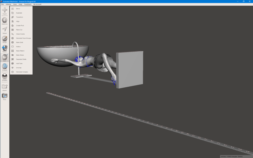
The next step is trying to make everything fit. Since the box is quite large, I decide that Anarani will hold it above her head, thus making the model even taller. I don’t want it to go in all three directions because that would require more machine space, thus making it more costly. The final height will be about 22 cm and it’s 75 mm wide and about 60 mm deep. (The sizes are from the bottom panel and the box.) The ruler is set up vertically so I can use that to scale it to the proper length, which would be 60 cm. I will then cut away the ruler from the model and thus have the exact height, although I don’t think the width and depth will change much from my prediction.

Anarani for blogpost III_0001

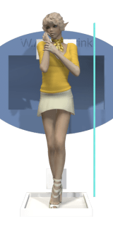
Anarani will look like this image. One foot on the floor panel and a second one against the back panel. Both feet touch these panels so they should be connected, although the support will be tricky.

The ruler has moved towards the back and will be used in one of the next steps to set the proper scale of the model, before I will remove it.

The box itself is held up by her arms. Here, the hands will need to touch the box to make sure that connection is strong too. But they can’t connect too well, else the fingers will disappear.

To get things at the proper size, I started with matching the ruler to the length of the back panel, which was 16 cm. I then used this to scale the box so the vertical height of the opening is 46 mm. If I did the math well, my device should fit just nicely.

Anarani for blogpost IV_0001

I have given Anarani high heels to wear and replaced her top with a bikini. This bikini top has a clothing thickness property allowing me to set the thickness of it, thus making sure it prints better.

The skirt she’s wearing is also special, since it is one of the few skirt models I have that has both an inside and an outside. Most clothing props for Poser tend to just cover one side and the render engine is smart enough to come up with the other side, if it needs to be rendered. But when you want to print those props, then the thickness is unknown and the repair function of Shapeways will actually fill it all up, thus turning the inside of a skirt into a massive block. With this skirt, I still have a skirt that you can look under.

I won’t tell if she’s wearing a bikini bottom!

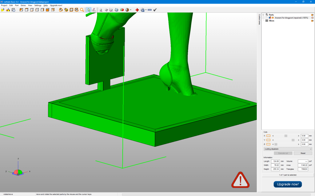
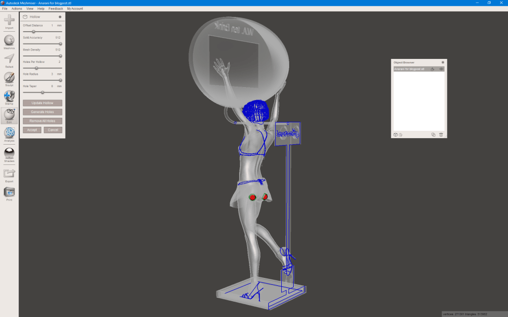
As an extra support for the box I used a cane prop from Poser and put it to the proper scale and thickness. It should add stability to the whole thing. making sure the bottom plate doesn’t bend over due to the weight of it all. Since there will be magnets on the back side, that bottom plate would not be supported and thus bend. This cane also required me to make Anarani bend slightly. After I put the hands in placed and locked their place, I moved her hip to the side and started to bend back her abdomen and chest to go near the cane again. Next, her neck was bent away from the cane and her head back to the cane so her neck and head (and hair, ear) would not touch the cane.

To make sure it is well-balanced, the whole box is in the center of the floor panel so it doesn’t matter that Anarani is leaning on her left foot. Gravity works downwards so the model won’t tilt to the left or right. Also, the border on top of the floor plane was added to make it stronger without making it much thicker.

I used a cane because the box is higher than the back panel. The cane adds a few more cm to this height. Add to this the height of the box (50 mm) and you get close to my estimation of 22 cm in total.

In my next post I will render the model in Vue, with some interesting textures, just to show what it will look like.

Print your own cases, part 3 of 10

In the earlier post I created a ruler so I can make sure that my box will have the exact size that I have specified. As I said, Poser loses this information, forcing me to fix the scale of the export file once I’m done with the model in Poser.

Temperature-Sensor
Mini Digital LCD Indoor Convenient Temperature Sensor Humidity Meter Thermometer Hygrometer Gauge

The device I will use is this thermometer that’s also shown on the left. (Image from AliExpress.) And the first thing I will have to do is measure it to get the exact dimensions. This is tricky because if you get the dimensions wrong, it either won’t fit or will be too loose to fit.

AliExpress does mention the size (3 cm x 4.8 cm x 1.6 cm) but these turn out to be incorrect! So, never assume the site will have exact measurements! Worse, this device has a small border that’s slightly bigger than the case itself, allowing a nice fit, but I need the size of the box, not the border. So, I take my ruler and start measuring the box. I end up with 45.75 mm x 25.9 mm x 13.5 mm. So, that’s the shape I need in OpenSCAD, which I will subtract from the real container.

The container itself needs to be hollow and must have enough space to contain the device. And for this one, I want a container that is round. That adds more complexity but it will look better. And I want my name on it, so people know it’s mine!

Making this shape isn’t difficult but you need to play around a bit. I did create the clock as a block to subtract from my shape and I did this to make sure that it fits. Especially the back should not have any holes from the corners of the device, otherwise, it won’t fit.

However, to create these oval shapes in OpenSCAD you need to create a round cylinder and a round sphere and then resize the width, height and depth to the required dimensions before subtracting the box. This slows down the rendering slightly, especially if you use high details.

And in the top of my script I use ‘$fn=250;’ which sets the detail level to a reasonable level. Simply put, OpenSCAD can’t create round shapes but can make a close estimate by using triangles and squares in a curve. With a value of 6, my shape would actually be a six-sided model. With 250, the round shape is actually made of 250 small, flat panels. Since I’ve set it to be 75 mm wide, those panels will be barely noticeable. Do keep in mind that the 3D printer won’t be able to make round shapes either so the value of 250 will be small enough to match the print resolution of Shapeways. But if you polish it, the shape will become more round.

Now, the script:

$fn=250;
module Box(){
  translate([-23, -13, 0]) union(){
    difference(){
      union(){
        translate([0, 0, 0]) cube([46, 26, 14]);
        translate([-2, -2, -2]) cube([50, 30, 2]);
      }
      union(){
        translate([23, 13, -0.1]) rotate([180, 0, 0]) linear_extrude(height = 2) {
          text("12:30", 
          size = 10, 
          font = "Lucida Console Regular", 
          halign = "center", 
          valign = "center"
        );
        } // text
      } // union
    } // difference
    difference(){
      translate([-2, -2, -3]) cube([50, 30, 2]);
      translate([0, 0, -3]) cube([46, 26, 14]);
    } // difference
  } // union
}

difference(){
  resize(newsize=[75, 50, 27.5]) union(){
    cylinder(d=75, h=2);
    difference(){
      sphere(d=75);
      union(){
        sphere(d=72);
        translate([0, 0, 2-75/2]) cube(75, center=true);
      } // union
    } // difference
  } // union
  union(){
    Box();
    translate([0, -19, 1]) rotate([180, 0, 0]) linear_extrude(height = 1) {
      text("W.A. ten Brink", 
      size = 4, 
      font = "Lucida Console Regular", 
      halign = "center", 
      valign = "center"
    );
    } // text
  } // union
}

This time I did not create a separate method for the texts simply because I use only two texts of different sizes. Creating a module for that would require an additional parameter and the text function isn’t that complex.

I first create the box including a border and make it look a bit pretty. I make sure that the box-part that needs to be subtracted aligns to the center of the X-Y plane and lies against the zero Z plane. The border will stick out anyways but it allows me an easier way to put it in the proper place. Because of this, I don’t need to translate the position of the box.

Please, do notice that the text on the box is offset at 1/10th of a millimeter because else a thin piece of those numbers will become part of the rendering! Those would become loose parts so I need to add an offset. This is something you have to do when you do into the negative parts. I should actually do the same for the border but actually like the small line that it adds. It won’t be really noticeable when printed, though. But in the 3D software it will be visible as a thin line.

The dimensions of this box are 75x50x27.5 mm which is a bit large. Then again, the device itself isn’t that small either.

Like the ruler, I uploaded this model to Shapeways to get an estimate of the price and looks. It has slightly more volume as my ruler but the price is more than double of my ruler! The reason for this is because the price for plastic is determined by the volume of the model and the machine space that it takes. And although my ruler was long, it was also thin and not so high, thus it did not need as much space as this model.

In my next post I will combine this model with my model Anarani. In that post, I will also create the platform for Anarani to stand upon, although that won’t be very special.

Print your own cases, part 2 of 10

In my previous post I mentioned that I need a ruler to use with my Poser models. The reason for this is very simple. When you export a model from Poser, the proper size of the model isn’t written correctly in the export file. Poser is a great application but it has troubles doing a proper export. As a result, you might think your model is 20 cm high but it happens to be just one millimeter. Why? Because Poser doesn’t write proper measurements.

Now, things are simple when you know what size your model is supposed to be. If you want your model to be 20 cm high then you just rescale it in MeshMixer and you’re done. However, if you have a box or case as part of your project, chances are that the model will be bigger in all directions than this box. The box might be 5 cm high but the model is 20 cm high. How to fix that problem?

Well, the solution is simple. Create a model of a ruler with tags for centimeters and millimeters. Make it very long so it will be longer than your model. And when you’re modeling in Poser, use the ruler next to the object that you need to have at a precise size. Scale the ruler so the size of the object matches the desired length. Do not scale the object to fit the ruler, though! You won’t need to.

When you have set the ruler to the proper scale, you can continue to work on your model. Make the ruler about twice the length of your model, which is 60 cm for me. When you do an export, keep the ruler part of the model but move it to the side or back so it can be cut away with MeshMixer or NetFabb. This will allow you to set the proper scale in MeshMixer to 60 cm as the height (or width, depth) of your model.

I want a simple ruler with small tags for millimeters and longer tags for centimeters. I also want the numbers for centimeters to be on the ruler so I don’t have to count. And I will number all the centimeter ticks too, just because I can.

$fn = 50;
length=300;
width=6;
thickness=1.6;
center=0.8;

module SetTag(number){
  linear_extrude(height = thickness) {
    text(number, 
    size = width/2, 
    font = "Lucida Console Regular", 
    halign = "center", 
    valign = "center"
    );
  };
} // SetTag

cube([length*2, center, width], center=true);
difference(){
  cube([length*2, thickness, width], center=true);
  union(){
    for(i=[-length:2:length]){
      translate([i, 0, (width-1)/2]) cube([1, thickness, 1], center=true); 
    } // for
    for(i=[-length:10:length]){
      translate([i, 0, (width-2)/2]) cube([1, thickness, 2], center=true); 
    } // for
    for(i=[-length+10:10:length-10]){
      translate([i, 0, -(width/8)])
      union(){
        rotate([90, 0, 0]) SetTag(str(i/10));
        rotate([90, 0, 180]) SetTag(str(i/10));
      } // union
    } // for
  } // union
} // difference

I created a special module to place the text on the ruler. I generally copy and paste it from my other projects since it defines my default settings for handling texts. You don’t need to do this but it makes the call to the text function easier.

I create two cubes for the ruler. One happens to be a thin part which makes the whole ruler solid. The other fattens the ruler so I can carve the ticks in the ruler without making parts too thin. This would allow me to even print my ruler, if I want to.

I’ve set up several variables so I can make as many rulers as I like, although the rendering can be a bit slow for long rulers. There are ticks carved for every 2 mm but you have to be aware that the middle of each tick is the exact place, not the left or right side of it. The zero tick is exactly in the middle, going half a mm in both directions. Keep this in mind since the ticks at 30 and -30 will be half the size of the other ticks. When you use the ruler to measure things in Poser, measure from the zero tick, not the ends of the ruler!

The numbers are at the proper spot, with all negative numbers on one side and positive numbers on the other.

Ruler

This ruler is very long but that’s the purpose of this ruler. I have uploaded it to Shapeways – Ruler and it is available there for about $7, excluding postage and taxes.

In my next post I will create the case for the thermometer.

Print your own cases, part 1 of 10

It’s about time I started blogging again and this time I just write a series of 10 parts explaining how I create small, plastic cases for all kinds of stuff. For example, like the battery container in a earlier post.

I like to use my 3D printed models as cases for my own electronic experiments. I’m still experimenting but things can be quite interesting this way. The things you create this way are unique. No one else has something like it, unless they can use your model to print their own cases. And this time I’m going to create a case for an electronic thermometer/hygrometer that I bought from AliExpress for € 1.28. And I want a pretty girl model to hold it up so I need to create a second structure to add stability to the whole model, since it would be top-heavy with the device high up. I will solve this by including space for a few 10mm round magnets that I have so I can put the whole thing against my whiteboard.

So, I will have a flat bottom with a small back panel that holds space for the magnets and a beam that will go up to give more support to the box. This beam will also hold a magnet on the top to better stick it against my whiteboard, else gravity will turn it upside-down. (Been there, done that!) An extra cylinder will connect the box to this beam so the model will be quite stable. That cylinder will need to be added in Poser since I don’t know where the box will be when I create it.

Anarani for blogpost
Anarani

But because I need exact measurements I’m also going to create a model for a ruler, so I can scale the ruler in Poser to synchronize it with the dimensions of the case. Why? Because Poser doesn’t create export files with proper measurements so you need to rescale them afterwards! Since I know the length of the ruler and since it will be the longest part, I should be able to fix the scale again to the proper length.

The model will be Anarani, who happens to just look pretty and I have printed her as a model before. She’s a small elvish character and she’s one of my favorite cyborg models. However, for this post I will use her without the cyborg parts. Anarani will be standing and holding the case at around her chest or higher. This means that the model will be tall and thin and I will later explain why that’s a good thing. (In short, it’s less expensive…)

So, with the model in my mind, I will also make an artistic rendering of the model just for the fun of it. It’s not complex but you will need to add textures to the case.

So, what software do I use?

  • OpenSCAD to create the model of the case. This is a very useful tool since you will be writing scripts with exact measurements and can generate very complex things from basically simple components.
  • Poser Pro for the Anarani model, since I want the case to be held by a pretty elf and that’s too complex for OpenSCAD.
  • E-On Vue for the artistic rendering of my model.
  • Accutrans 3D to remove unwanted parts from the model and to remove all textures and merge all parts into a single model.
  • MeshMixer to set the scale of the model and to make it hollow. Meshmixer can also be used to put the model correctly upright, facing in the proper direction.
  • NetFabb Basic to do some more, automated repairs. Especially important when working with Poser models since Poser models aren’t made to be printed but rendered.
  • MeshLab as an alternative solution to repair models.

And finally I will send the model to Shapeways where it will be printed in white plastic. Other materials are also possible but white plastic tends to be the cheapest and strongest material. You can use sandstone and even colored sandstone, but sandstone isn’t very practical if you have small details like fingers, toes, noses, etc. Sandstone is great for making e.g. a bust of a model at a large size. However, sandstone requires walls of at least 2mm thick. Plastic can be as thin as 0.7mm…

In the end, I want to have a 3D printed model of about 20 cm high that I can put against my whiteboard and it will tell me the humidity and temperature.

So, that’s the plan. Let’s get started in part 2!

Making 3D prints with OpenSCAD, Poser and Shapeways.

As you might know, I’ve played for years with Poser Pro now. And for about a year, I have created printed models through the services of Shapeways while also creating all kind of artwork with those Poser models and E-ON Vue. But more recently (well, less than a week ago) I started experimenting with OpenSCAD, which is an open-source CAD application where you just “program” a special script file and it will generate a 3D model for you based on that script.

So, to start I will show you how I created a special box for my electronic experiments, which is my Shapeways model. It is a rectangular box with five holes in the side for wires that lead to a small, round container. Not sure what I want to build inside it, but I just like the shape and it is a nice experiment to start with.

This is a box with two different lids. One round, one rectangular. The rectangular lid will also contain a small engraved text.

To start, I create a simple module to create the lid:

module BoxLid(width, height, depth, groove){
    union(){
        cube([width, height, depth/3]); 
        translate([groove, 0, depth*1/3])cube([width-2*groove, height-2*groove, depth*1/3]);
        translate([groove/2, 0, depth*2/3]) cube([width-groove, height-groove, depth*1/3]);
        translate([width*6/20, groove*1, -depth*1/3]) cube([width*8/20, groove/2, depth*1/3]);
        translate([width*7/20, groove*2, -depth*1/3]) cube([width*6/20, groove/2, depth*1/3]);
        translate([width*8/20, groove*3, -depth*1/3]) cube([width*4/20, groove/2, depth*1/3]);
    }
}

This set of cubes will create the lid that will slide in a special slot that we will add to the box. The first three cubes are of various sizes and create a groove to slide over. The lid will completely cover the side of the box.

The last cubes are used to put some relief on the lid to allow it to slide easier up and down. But I want to have it engraved with some text, so I create an engraving module:

module label(name, depth, fontSize){
    linear_extrude(height = depth) {
         text(name, size = fontSize, font = "Lucida Calligraphy", halign = "center", valign = "center", $fn = 50);
     };
}

And I need a second module for the lid including the engraved name:

module NamedBoxLid(width, height, depth, groove){
    difference(){
         BoxLid(width, height, groove, groove);
         translate([width/2, height/2, groove/2]) rotate([0, 180, 270]) label("Team Katje", groove, 8);
     }
}

Yeah, engraving is just that simple! Subtract the shape of the text from the shape of the lid. The most tricky part is actually trying to rotate it and making it fit. But it also tells us how we can create a box. We basically make a box and subtract the lid from it! I will also subtract 6 cylinders from a side for the holes to the round box on the side. And we will also subtract the inner space from the box so it has space:

module Box(width, height, depth, groove){
    difference(){
         cube([width, height, depth]);
         union(){
             translate([groove, groove, groove]) cube([width-2*groove, height-2*groove, depth-2*groove]);
             translate([width*1/5, groove*3/2, depth/2]) rotate([90, 0, 0]) cylinder(h=groove*2, r=groove*2, $fn=precision);
             translate([width*4/5, groove*3/2, depth/2]) rotate([90, 0, 0]) cylinder(h=groove*2, r=groove*2, $fn=precision);
             translate([width/2, groove*3/2, depth*1/5]) rotate([90, 0, 0]) cylinder(h=groove*2, r=groove*2, $fn=precision);
             translate([width/2, groove*3/2, depth*4/5]) rotate([90, 0, 0]) cylinder(h=groove*2, r=groove*2, $fn=precision);
             translate([width/2, groove*3/2, depth/2]) rotate([90, 0, 0]) cylinder(h=groove*2, r=groove*2, $fn=precision);
             BoxLid(width, height, groove, groove); 
         }
     }
}

Or actually, I combine the five holes, the box content and the lid together into a single shape and subtract the whole shape from the box. This way, I know the lid will fit perfectly on the box.

All I have to do now is create the second, cylindrical box on top of the holes. For this, I again start with creating a lid:

module CylinderLid(width, groove){
    union(){
         cylinder(h=groove, r=(width-groove*2)/2, $fn=precision);
        translate([0, 0, groove])
         difference(){
             cylinder(h=groove, r=(width-groove*2)/2-groove, $fn=precision);
             cylinder(h=groove, r=(width-groove*2)/2-groove*2, $fn=precision);
         }
     }
}

Again, a simple procedure of stacking two cylinders on top of each other. However, to make slightly more room, the smaller cylinder is hollowed by subtracting an even smaller cylinder. The result is a ridge to keep the lid in place.

And like the box, I will subtract the cylinder lid from a hollowed cylinder:

module CylinderBox(width, height, groove){
    difference(){
         cylinder(h=height, r=(width-groove*2)/2, $fn=precision);
         union(){
                 CylinderLid(width, groove);
                 translate([0, 0, groove]) cylinder(h=height-groove, r=(width-groove*2)/2-groove, $fn=precision);
         }
     }
}

Now I know that the cylinder plus lid will be exactly the proper height together. All I have to do now is put them all together:

width=40;
height=80;
depth=width;
groove=2;
cylinderhight=12;

Box(width, height, depth, groove);
translate([0, 0, depth+3]) NamedBoxLid(width, height, depth, groove);
translate([width/2, groove, depth/2]) rotate([90, 0, 0]) CylinderBox(width, cylinderhight, groove);
translate([width/2, height/2, depth+10]) rotate([180, 0, 0]) CylinderLid(width, groove);
translate([width/2, height/2, depth]) cylinder(h=10, r=1, $fn=precision);

I first specify the sizes for the box in millimeters. It will be 4x4x9.2 CM in size, which is large enough for a 9 volt battery plus holder, some wires and maybe some other stuff.

Next, I create the box at the standard location. Above the box, I put the lid, with some space in-between to keep them separate. The cylinder is put against the box itself around the holes but the lid for the cylinder is put on top of the lid for the box itself.

The last thing connects the box and the two lids to make it all a single part. On Shapeways, you have to pay extra if it is all separate parts so make sure you connect it all together with thin connectors that you can easily cut away with a sharp knife. And yes, I checked to make sure it doesn’t go through the line of text on the lid!

Now, what does it all look like? Well, just look at these images:
LidBoxCylinderLidBatteryBox

It is all quite easy to do, although it requires plenty of math to get things in the proper locations. I haven’t explained the math part and I won’t. I’m just showing what you can do with OpenSCAD and a few hours of free time.

The result is a .STL file that you can upload to Shapeways to have it printed. As an alternative option, you can also convert it to an .OBJ file format and import the box into Poser, and add a Poser model on top of the cylinder lid, just for fun.

Or you will add textures to the shape and use it in Poser/Vue to create some new image. It can be even more interesting if you can combine a 3D printed model together with a rendered image of the same model.

I still have a lot to learn about OpenSCAD but this tool allows you to specify exactly the shapes that you want for your 3D model and allows you to create modules that will allow you to do some complex things like separating a lid from a box.

Making a hollow model for Shapeways.

I like Shapeways! You can use them to generate prints from 3D models that you design. However, at first I wanted to create 3D models with some extra hollow closet or whatever else to use for some small electronics. Problem is, these adages will also add more material and space, thus increase the price. So I decided to just create hollow busts from my model so I still have some hollow area but also a nice model without any other props.

To start, I use a few pieces of software. First of all, Poser Pro with more models. Although a little old already, I still prefer to use the Victoria 4 model from DAZ3D. With some extra shapes and textures, you can make some very beautiful models.

Next, I need a tool for handling and converting the 3D models. Here Accutrans 3D does a lot of magic for me, including minor fixes and allowing me to fix any textures. It also allows me to merge parts that use the same texture, which makes everything a lot simpler.

I use Netfabb for repairs, scaling and to cut the model in half, so I get a bust instead of a whole model. The free version is good enough for my purposes.

And I use Meshmixer to make the bust hollow and thus reduce the amount of material required.

So I start with creating a model and putting her in a proper pose for my bust. Poser can do that real fast and, what the heck, let’s keep her topless! I just want a simple example. And when the pose is done, I need to save it three times! First, I save the original pose as a Poser file. That way, I can make adjustments to the pose later on. Second, I do an export to the Collada file (.dae) format. Poser doesn’t do a good Collada-export, though, but it will copy all the used textures to my save folder, in a subfolder called textures! And I need those copies later on. The third file is a Wavefront file (.obj) which I will import in the next tool, after I copied the textures from the subfolder to the save folder.

Abby_0001

So, this is what Abby will look like. Even though she is topless, I just kept the “naughty parts” hidden for my blog.

A few notes: Abby is a female Elf and I have used her for several CGI images already. I have never used her for a print, though. This will be interesting because her hair might not print as well as I hope, but this is all just a test.

Keep in mind that Shapeways has a Content Policy that is a bit strict when models are nude. Nudity is allowed as long as it is artistic by nature. However, the definition of “artistic” is up to the person reviewing the model and chances are that your model will be refused because they don’t think it is artistic enough.

Now I will have to merge the various parts for this model and maybe remove a few things that disturb my model. To begin with, my model will have a layer called “Cornea” and one called “EyeSurface”. Normally in Poser, those would be transparent and thus not visible, except for some extra shininess or added reflections. Unfortunately, they became visible in my model so I generally remove these layers. Also, there are “Eyelashes” that generally either lack a texture or are just completely black. I remove those too, in general.

Screenshot 2015-11-13 18.12.54Screenshot 2015-11-13 18.15.52

Once done, I use “Tools_1/Merge layers with same materials” to reduce the number of layers in my model. Then I save it to a new folder in two different formats. First of all, Collada, so I have a copy that I can use for this model. Next, a Wavefront file for further processing.

The next step is scaling and the first cut. Netfabb does a great job at this, keeping the textures intact!

Screenshot 2015-11-13 18.22.17Screenshot 2015-11-13 18.23.43

As you can see, the complete model is naked, but that’s not a big problem. The bottom half will be cut away anyways. But first some scaling. The Y size is the largest value at 0.57 mm, which is very, very small. I’ll change it to 600, making the model about 60 CM high. I will then export the file to a new folder in Wavefront format again, and it will be saved including new texture files.

Now, I will make her hollow by using Meshmixer. Basically import the Wavefront file that Netfabb created and choose “Edit”Hollow” and the system will generate a hollow space inside your model.

Screenshot 2015-11-13 18.41.36

Once you like the hollow area, accept it and export it to another new folder as Wavefront format. Because now we will have to make a cut! So we have to import the file in Netfabb again. And do a cut!

Screenshot 2015-11-13 18.47.59

Although we’re only interested in the top half, I generally rename both parts (e.g. “Abby Top” and “Abby bottom”) so I can always decide to have both sides printed! With some glue, you can glue them together again.

But what does the result look like?

Screenshot 2015-11-13 19.12.29Screenshot 2015-11-13 19.30.28

I’m a bit annoyed that the textures weren’t saved after I made the cut. Then again, I would like the print to be in white plastic anyways. The colored sandstone would not be strong enough to hold the thin walls and the colored plastic has a size limitation, which is a bit small to me. So this last white result is fine. I also show the bottom half but Shapeways will have some minor troubles with that part. The arm is not connected to the rest of the body so it would become two parts.

And the bottom part is nude, thus a possible content policy violation.

The last step is the upload to Shapeways. This is a bit slow but since I kept the model reasonable simple, I should have a result within a few minutes. In the meantime, do keep in mind that Shapeways will charge for the amount of machine space and not just material space when printing in white plastic. Thus, while the hollow model will require less material, you will still have to pay for the large size. And since the original size resulted in a print of $400, I reduced the size by 60% on Shapeways, which reduced mostly the amount of machine space. The price is now around the $100, which is still a lot. But hey! I have a hollow model now.

I could also upload the bottom part, reduce it by 60% and have both parts printed to get a complete model, which I have to glue together. But once I do that, I will likely use a nicer model instead. For now, I’m still doing a lot of experiments and I try to avoid printing a lot of them, since these prints are expensive.

The final result.

Update

So, what does the final result look like?

As you can see, the model is about as large as my cup of tea. I can insert an RGB-led inside it to make a very colorful display. Not all parts are hollow, though. Her right arm is solid from slightly above the elbow. Also, I kept her mouth and teeth part of the model, so they became part of the solid areas too. So yeah, her teeth are printed too but you can’t see them. And the skullcap and hair was also made one solid piece though her head, as part of the auto-repair or whatever. This makes her top a bit heavy but it is still stable enough to stand.

I also learned that scaling and cutting a model can be done from Meshmixer quite well and that too gives great results. With Meshmixer you can also add holes to a hollow model so you don’t have to cut it in two parts. The small hollow spaces would allow the unused material inside the model to fall out. But then you will have a model with small holes in it.

As I have been experimenting with these pieces of software, I’ve learned that Netfabb has a great repair function similar to what Shapeways uses. All three apps together make some pretty powerful tools for anyone who wants to create 3D models to print.

Four models on Shapeways (NSFW)

I like Shapeways since you can upload your own 3D designs and end up with a 3D printed model. This allows me to e.g. create custom boxes for small hardware experiments. These boxes are combined with my Poser models and will thus result in very interesting designs. But like everything with 3D, you will have to do some experiments first. I created three new models in Poser named Nora, Tommi and Cassiopa and I used some interesting trick to create a special rack to include in the pose. But first, let’s look at Nora:

WIN_20151026_102324 WIN_20151026_102455

Nora was printed in two versions: White plastic and Colored sandstone. And in both models a few flaws were already visible. Nora’s shoes were made of a very thin material and the upload to Shapeways did a repair that removed the very thin parts. As a result, the shoes are flawed.

WIN_20151026_102331 WIN_20151026_102500

Well, a bit of glue and plastic can fix that. But her fingers were also a bit delicate and the sandstone version ended up with broken fingers because the fingers are actually too thin. Again, some glue and they’re back in place.

WIN_20151026_102352 WIN_20151026_102505

Her thumb is still missing, though. Then again, I was more interested in checking how well the 3D printer handles holes, like the area where she keeps her left hand. In front of her genitals, to keep it decent, yet far away so it doesn’t touch. Combined with the position of her legs, this results in a complex hole to print but it ended up flawless. Even her left hand was intact.

WIN_20151026_102409 WIN_20151026_102511

So, what I’ve learned from Nora is that thin elements like fingers and shoes won’t print very well. White plastic does a better job than sandstone, though. That’s because sandstone needs further processing after the printing is done, which requires some manual labour. Thus, small parts can end up being damaged.

Another part that’s important with the sandstone version is the textures. For this, I will check her face:

WIN_20151026_102344 WIN_20151026_102524

And in case you’re wondering why her hair is covered by a towel, well… Hair really doesn’t print very well. It tends to generate loose shells or often to parts that are too thin to print. Besides, the towel makes her look as if she’s just out of bath, relaxing.

The White plastic versions shows a reasonable amount of details in her face. Even her open mouth is printed quite nicely. The sandstone model also has an open mouth and you might see her tongue and teeth if you look inside with a microscope. But I’m more looking at her face and eyes.

Printing in colored sandstone has an ink density of about 50 DPI. Normally, a printer would print at 300 DPI so the colors will lose details. But I chose a light-colored iris and Nora has good-looking pupils in this print. Which is important to remember, since dark eye colors might darken the whole eye. It still looks good in my opinion. At least better than what I can do with paint and a brush.


The next model is Cassiopa. Since I know that thin parts won’t print well, I’ve placed her on a towel, hoping for a better result. The result is okay but the sandstone version did not survive the print because the towel was too thin. So I uploaded a newer version of Cassiopa on a more solid floor and in this version, I also adjusted her clothing. Why? Because I need to test more than just panties on topless women. Still, the white plastic version looks okay, although it is a bit small:

WIN_20151026_102632 WIN_20151026_102652 WIN_20151026_102700 WIN_20151026_102817

The model was almost 15 CM long, but that’s the length of the towel. Cassiopa uses only 2/3rd of this length, thus she’s smaller than my other models. (This also happens with one of my Tommi models.) Smaller means that fewer details will be visible but it is still detailed enough.

The towel she’s on has a hole in it, which is too bad but I’m not too worried about it. I now know that I can’t use these kinds of thin plateaus for my models to rest upon. In the sandstone version, the towel had crumbled away.


The last model is Tommi which I’ve combined with a rack. I made a second version of Tommi climbing this rack but Tommi herself becomes small if you do this, thus losing details. Let’s look at the climbing version first:

WIN_20151026_103142 WIN_20151026_103151 WIN_20151026_103216 WIN_20151026_103233 WIN_20151026_103242 WIN_20151026_103256

I gave Tommi a skirt instead of panties so you should have been able to look up her skirt. However, Shapeways repairs this automatically and as a result, the skirt became solid. And that’s a flaw in the skirt model.

This is a colored print so her texture helps to add details, but she’s too small to be very clear in details. She did have a flaw in her right hand, since her fingers were too thin and either did not get printed or broke off afterwards. A bit of paint will fix that, though. It is just something to remember.

So, remember: make sure thin parts are well-supported and preferably resting against something else and with clothes, be aware that Shapeways might fill in specific areas that you’ve hoped would stay hollow. In this case her skirt but I also tried another interesting top on Tommi but that added a white mass over her breasts since Shapeways was filling the area between the left and right cup.

Next, the bigger version of Tommi with her resting upon the rack. That one was perfect, although one of the legs from the rack had broken off during transport. So, even if a part is thick enough to print, it might still be very vulnerable. With a length of over 4 CM, they can’t handle a lot of stress. Still, this model is great with no broken appendices and even her toenails are visible!

WIN_20151026_102904 WIN_20151026_102914 WIN_20151026_102958 WIN_20151026_103102

Well, at least I glued the leg back in place. I might decide to remove all four instead, though, if I fear they will break again. This model happens to be quite heavy too, which makes sense since she has the biggest volume of all. Her eyes are nicely detailed and her skin color even has some variation around her knees. And you can see her toenails! A bigger model is nice in that regard so if your model has a lot of fine details, have it printed in a larger scale! Although the price will scale up too, since more materials will be required.

Well, these three models all look reasonable well and taught me what I need to know about printing Poser models: use a reasonable large-scale, support all small parts and be aware that hollow spaces might end up being filled with extra material because Shapeways “repairs” some thin materials.

I kept these models mostly undressed because I know the textures of these models and needed to see how the color printing will support the texture details. Also, it is difficult to find Poser clothing models that are working well when uploaded to Shapeways. These models are not made to be printed in 3D but to be rendered. So finding good clothes to print is difficult. For Victoria 4, her bikini top and bottom do print quite well, though. They too are filled up, but the filling it towards the body of the model and not between both cups.

Another problem is the limitations on models set by Shapeways. There’s a size limit and there’s a polygon limit. (64 MB or 1 million polygons.) Poser models can easily go over this amount of polygons so you will have to find a way to reduce those, while keeping textures intact.


And then there’s the rack used by both models. The rack is the same length for both and I’ve created it myself by using the Firestorm viewer with the Second Life virtual worlds, but I could have used my own OpenSim world too. I just joined several cylinders for the rounded sides and balls for the rounded corners to build the framework. I also created a square plane with a hole inside, which I copied three times and put next to one another. I then exported the whole model from the SL viewer to a Collada file, which I imported in AccuTrans 3D to clean it up a bit and to reduce the complexity of it. (For example, by merging all parts into one single part.)

And then I checked if the rack has enough space for other hardware.

WIN_20151026_104131 WIN_20151026_104323

Well, the rack isn’t wide enough for an Arduino board

Since I copied the square plane three times, I had expected all holes to have the same size. And the rack was made so I can add some hardware in the empty rack space and have some wires or other parts move through the open holes to e.g. shine a LED light on the model. So, I was surprised when I discovered that the middle hole was slightly bigger than the other two. Which I discovered by trying to fit an Arduino-board. (The YUN is shown in the picture.) The length is long enough for the Arduino Mega but it will have a few millimeters on the sides of the rack. The pins are actually at the exact location of the long bars. So you could actually put an Arduino in the rack if you don’t mind the width.

But smaller devices like the Arduino Mini, the Trinket, the NetDuino mini and the Digispark have plenty of room inside the rack.

But back to the holes!

WIN_20151026_103544WIN_20151026_103535 WIN_20151026_103705 WIN_20151026_103853 WIN_20151026_103920 WIN_20151026_104434

Using the climbing Tommi version, I used to try a green LED. It doesn’t fit the top or bottom hole but it does fit the middle hole. Trying it again with a regular lamp of 5 MM diameter, I see it going through the middle hole without effort but the top and bottom ones don’t fit. A laser light won’t even fit the middle hole, though.

The conclusion is that these holes are a bit too small for LED lights. No problem, since I can take a drill bit and make them wider. Still, I had hoped they would be big enough for a LED light. So I have to redo my calculations. And I have to wonder why the middle hole is bigger than the other two, while they’re basically all the same in my 3D software.

Anyway, I now have two great models for containing some of my experimental hardware. I know the racks are open so the hardware would be exposed but that’s something I will solve with a next version of my rack. I also know how thin the walls can be and how thin the walls of my rack are. I can still have the rounded areas but the rack should get more solid walls. Thin walls too, since the rack has a lot of volume.

Next, the question what I would like to create with these models. Whatever I think of should match the model. The three holes in the rack are meant for lights, cables, buttons or something else but I don’t want to show too much hardware on the model side of the rack. I also need to find a solution to attach the additional hardware to the rack, since it doesn’t have any special pins or whatever to hold them. Then again, these models were created to see how well these racks would print. The different hole size was a surprise for me which I need to include in my calculations.

And the three rack-less models? They’re just nice desk ornaments.I have ordered more prints so I will likely have more ornaments soon.

My next designs will have better racks, preferably with extra points to hold my hardware in place. The sandstone prints still look great but I have to consider the size of the whole thing. And I will need to experiment with clothing, to see which items will print best. The same is true with hair, since I still have to find hair that prints well in 3D.

All in all, 3D printing is a very interesting challenge. Slightly expensive too, though.

@Shapeways White plastic print

I started a new model called Ruby and wanted a 3D printed version of it. The original model is here, created with Poser Pro and rendered in Eon Vue just to make a pretty image to compare the rendered image with a printed version.Ruby Poses (Small)

I wanted a colored print but the arms and legs are too fragile for sandstone and the model has too many thin walls for colored plastic. So I wanted to know what it looks like in white plastic.

Torso

For additional comparisons, I used pictures of the printed model and a rendered image of the model in color and in white. The print is a bit grainy because the small print particles that make up the model are still a bit large. Smaller particles would generate a more smooth surface in my opinion but it would also take a lot longer to print.

Face

This shot above displays how textures give shape to her hair. Even the white version has a texture setting some of the transparency, giving it some shape. This gets lost in the printed version, since 3D printing only works with shapes, not textures.

So, how about the rest? Front and back, right hand and left hand, right foot and left foot. The ruler in the front picture shows the model is slightly less than 20 cm high. The details look great, though. Even though the surface isn’t smooth, you can still see a lot of the original model in the print.

Her shoes look great though, even considering that these are the most vulnerable parts of the print. The straps are not connected to her foot and her toes are quite detailed. And I made her hands have a fistlike-shape but with some hollow area in them so that she could hold something in them. Which is exactly what I wanted. Now, I have to think about what she’s going to hold, though.

The next step is deciding how to continue with this model. I would like to paint it but that won’t be easy. Part of her face is barely reachable with a thin brush and making her look realistic would also be challenging. I’m a Software Engineer, not a Painter! So I’m probably keep her like this and make her hold two LED lights with a battery box and a switch and she would become a cute light. This will be fun!

[Update]

I added a battery container, a switch and two lights to the model and added a picture of the result below. The wires are intentionally visible and so is the battery pack and switch. It did not require a lot of components but I did get to use my soldering iron and my glue pistol to get things in the proper place. (The switch is that blue thing on the bottom-left.)

These aren’t very bright lights but I did not want any bright lights!
Front BackRight handLeft handRight footLeft foot

WIN_20151012_001556

VIP wijn (Van @VIPInternet!) (In Dutch, sorry.)

Vandaag ontving ik een mooi, groot pakket van de postcode. Dat gebeurt regelmatig maar dit pakket was een beetje onverwacht, hoewel de afzender mij wel bekend klinkt.
DSC05004

De afzender is VIP Internet waar ik diverse domeinnamen heb geregistreerd waaronder de naam van mijn blog. Jeweetwel, wat je nu leest. VIP bestaat dit jaar namelijk 15 jaar en dat wilden ze vieren dus hebben ze een aantal pakketten verloot aan hun Twitter-volgers. Ik volg ze op Twitter dus ik had een kans. En ik won!

DSC05005

In de verpakking zat een mooi houten doosje met een bijbehorende brief. En ja, dat is een kist met wijn erin, maar welke soort wist ik nog niet meteen. Maar eerst, de brief lezen!

DSC05006

Ze bestaan al 15 jaar en ik heb al geruime tijd bij hen het een en ander geregistreerd. In het verleden heb ik zelfs een website door hen laten hosten maar tegenwoordig gebruik ik mijn eigen server daarvoor. Plus een virtuele server ergens in de Cloud. Plus Microsoft Azure. Eigenlijk gebruik ik ze alleen voor domein-registratie en het beheren van de bijbehorende DNS gegevens. En dat gaat heel goed.

DSC05007

En dan de wijnkist. Hierboven de kist nog in de doos, en hieronder buiten de doos. Een mooie kist, overigens.

DSC05008

Natuurlijk blijft de vraag over wat ik met het kistje ga doen zodra de wijn op is. Ik vind het altijd zonde om ze weg te gooien. Misschien dat iemand er een mooi vogelhuisje van kan maken, of zo? Ik zie wel! Maar eerst, de wijn!

DSC05009

Oh, nog meer brieven en er zit een fles ondersteboven in het kistje. Ziet eruit als rode wijn. Dat heeft wel mijn voorkeur, hoewel ik wijn meestal gebruik als ik een biefstukje bak en de just ga blussen met wat vocht. Rode wijn geeft een iets zoetere smaak aan de jus en maakt deze donkerder.

Maar dit is een drinkwijn, geen kookwijn…

DSC05010

Er zitten twee wijnflessen in. Een witte Merle Blanc de Chateau Clarke en is vanaf 2015 drinkbaar en houdbaar tot 2018. Ik denk dat dit een mooie fles is om met de Kerstdagen aan te breken.

De rode wijn is een Merlot, ook van Chateau Clarke, natuurlijk. Deze is al sinds 2014 drinkbaar en houdbaar tot 2025. Een mooie fles om het nieuwe jaar mee te gaan vieren!

DSC05011

En daar zijn de twee flessen met gefermenteerd druivensap. Ze zien er best mooi uit.

DSC05014 DSC05015

Even de etiketten goed lezen. Mooie, Franse wijnen, dat moge duidelijk zijn. De witte wijn moet eigenlijk gekoeld worden tot 12 graden maar rode wijn drink je gewoon op kamertemperatuur. Ten minste, zolang het maar niet tropisch warm is.

Altijd ook leuk om te zien wat ik nog weet van mijn lessen Frans van vroeger. Gelukkig heeft de rode wijn tevens een Engelse vertaling, want mijn kennis van de Franse taal blijkt nog steeds even slecht te zijn…

DSC05016

Ziehier, de twee flessen wijn die ik bij VIP Internet heb gewonnen. Ik ben er best blij mee want met de feestdagen komen ze prima van pas. En voor diegenen die willen weten welke fles mijn favoriet is:

DSC05017

Tja, sorry. Ik drink eigenlijk vrij zelden wijn. Een glas cola vind ik namelijk net zo lekker bij de maaltijd. Maar bij een speciale maaltijd hoort geen cola, maar gewoon een mooie fles wijn. En die heb ik nu! Geloof mij maar, ze komen wel op rond de kerstdagen. Ze zien er lekker uit en zijn best goed van kwaliteit. Ik ben er dan ook best blij mee.